Cable connector

a cable connector and connector technology, applied in the direction of coupling device connection, coupling/disconnecting parts, electrical apparatus, etc., can solve the problem of difficult miniaturization of the connector, and achieve the effect of simplifying the connector structure, reducing the force applied to the actuator, and connecting easily and surely

Inactive Publication Date: 2009-06-25
MOLEX INC
View PDF13 Cites 6 Cited by
  • Summary
  • Abstract
  • Description
  • Claims
  • Application Information

AI Technical Summary

Benefits of technology

[0012]In the cable connector according to a still further embodiment of the present invention, the actuator is provided with a pivotal shaft for allowing the actuator to be pivotally moved thereby changing the attitude thereof between the first position and the second position, and the pivotal shaft supports, together with the distal end-side arm portions, a repulsive force generated when the actuator at the second position applies an urging effect to the free end portions of the terminals.
[0013]In accordance with the present invention, the connector urges the electrodes towards the cable by the use of the elasticity exhibited by the end side portions of the respective terminals. Hence, a force applied to the actuator can be reduced and dispersed. Furthermore, since there is provided such a configuration that the pivotal shaft of the actuator is pressed down, over its length along a direction of the pivotal shaft per se, by the distal end-side arm portions of the respective terminals, the whole actuator can be reluctant to be buckled when the actuator comes to the closed position thereof. Therefore, in spite of the simplified structure of the connector, the cable can be easily and surely connected to the connector per se without causing any deformation of the actuator. Further, it is possible to increase the width of the connector so as to attain a multi-way construction while effecting a reduction in the thickness and the size of the connector.

Problems solved by technology

This makes it difficult to miniaturize the connector.

Method used


Image

  • Cable connector
  • Cable connector
  • Cable connector

Examples


Embodiment Construction

[0027]A preferred embodiment of the present invention will be described hereinbelow in detail with reference to the accompanying drawings.

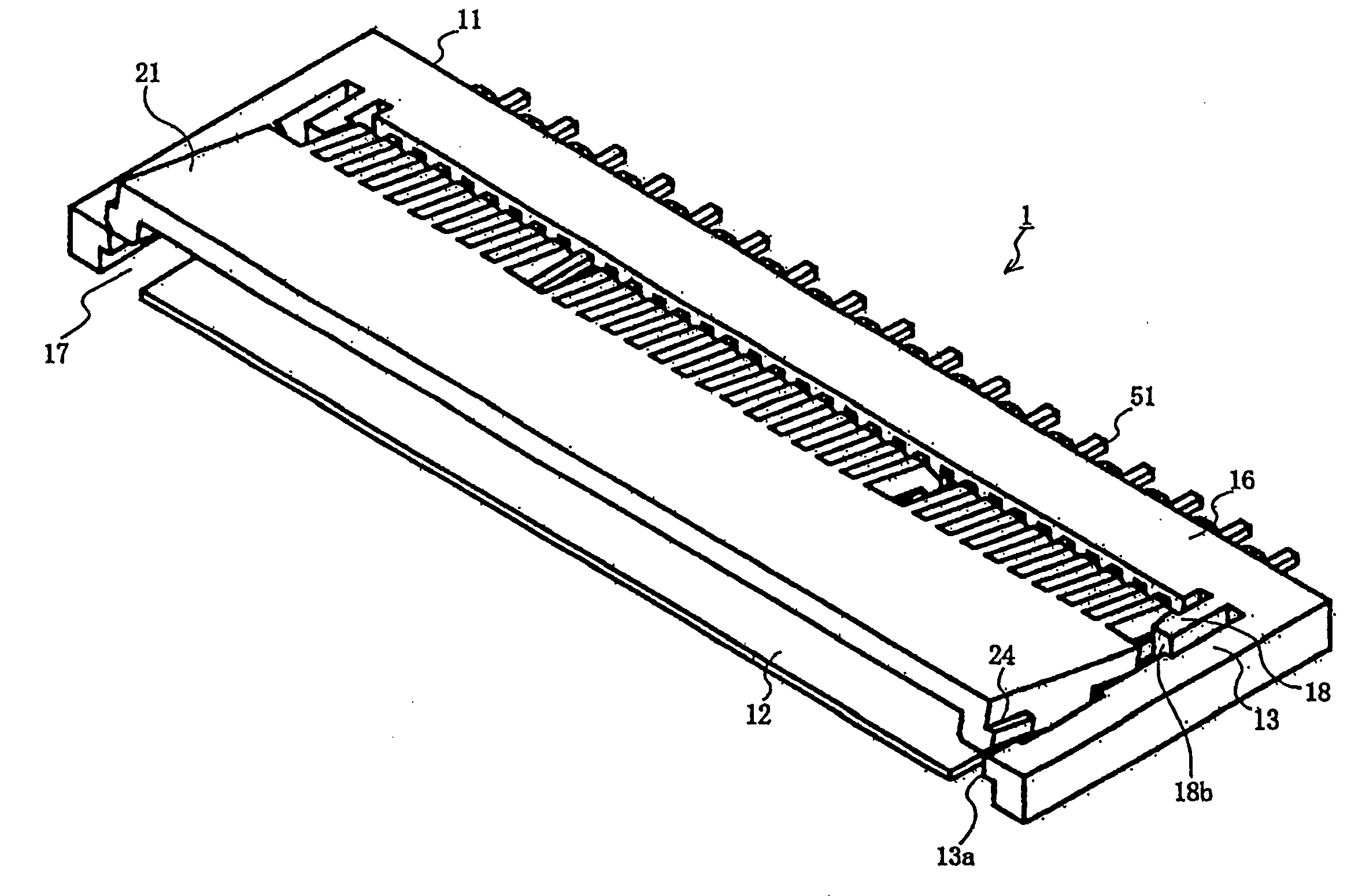
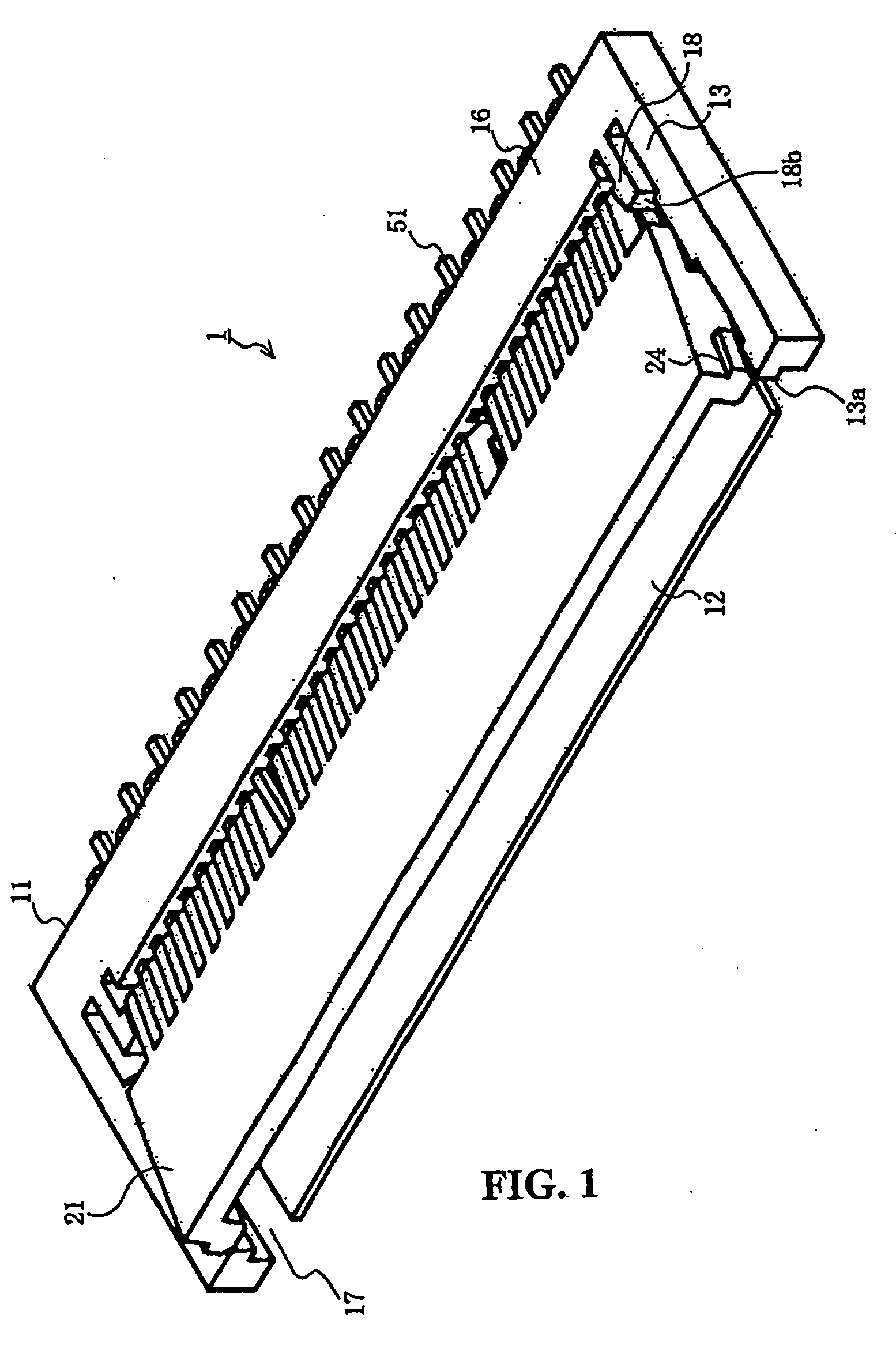
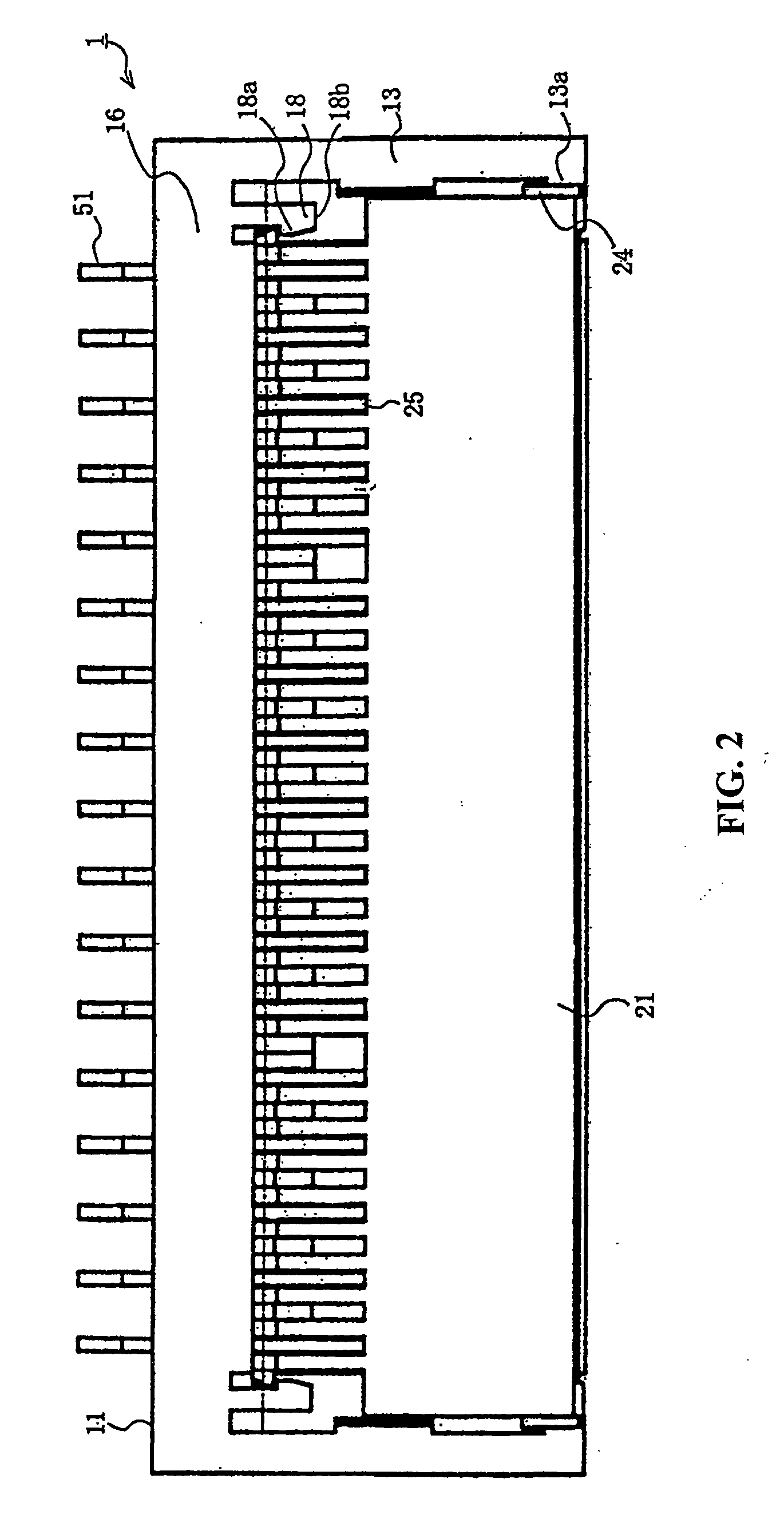
[0028]FIG. 1 is a perspective view of a connector according to an embodiment of the present invention, FIG. 2 is a top plan view of the connector according to the embodiment of the present invention, FIG. 3 is a front view showing a portion of the connector according to the embodiment of the present invention, FIG. 4 is a first cross-sectional view of the connector according to the embodiment of the present invention, taken along the arrow X-X of FIG. 3, FIG. 5 is a second cross-sectional view of the connector according to the embodiment of the present invention, taken along the arrow Y-Y of FIG. 3, and FIGS. 6A, 6B, and 6C are views showing an actuator according to the embodiment of the present invention, wherein FIG. 6A is a perspective view, FIG. 6B is a top plan view, and FIG. 6C is a bottom surface view.

[0029]In the drawings, reference numera...


PUM


Abstract

A cable connector includes a housing into which a cable may be inserted. A plurality of terminals are mounted on the housing and include an elastically-deformable arm portion with a free end section and a distal end section; and an actuator mounted on the housing and movable between a first operative position and a second operative position wherein the actuator urges the contact portion of each terminal towards the cable upon insertion of said cable into said insertion opening and movement of said actuator from said first operative position to said second operative position.

Description

BACKGROUND OF THE INVENTION[0001]The present invention relates to a cable connector. Conventionally, a connector for connecting a flat plate-like cable such as a flexible circuit board, a flexible flat cable or the like has been proposed (refer to, for example, Japanese Patent Application Laid-Open (Kokai) publication No. S63-218175).[0002]FIGS. 13A and 13B are cross-sectional views of one conventional cable connector.[0003]In FIGS. 13A and 13B, reference numeral 801 designates a body portion which is formed of an insulating material and includes a receiving portion 804 into which a circuit board 807 is inserted. To the body portion 801, distal ends of terminals 802 formed of a conductive material are fixedly secured, and a movable portion 803 is pivotably connected. In each of the terminals 802, a projecting portion 805 to be connected to the circuit board 807 is formed, and a projection 806 to come into contact with each of the terminals 802 at a position in the vicinity of a free...

Claims


Application Information

Patent Timeline
Patent Type & Authority Applications(United States)
IPC IPC(8): H01R13/62
CPCH01R12/79H01R12/88H01R12/82
Inventor NIITSU, TOSHIHIRO
Owner MOLEX INC
Why Eureka
Try Eureka