Combination cabinet

a technology of combinatories and cabinets, applied in the field of combinatories, can solve the problems of fixed distance between the separation plates and inability to freely adjust, and achieve the effect of stable state structure, easy and quick adjustment, and easy vibration

Inactive Publication Date: 2014-04-29
CHEN SHUN TENG
View PDF29 Cites 4 Cited by
  • Summary
  • Abstract
  • Description
  • Claims
  • Application Information

AI Technical Summary

Benefits of technology

[0007]According to the primary advantage of the present invention, the upright posts and the crossbars are combined together solidly and stably by interaction of the connectors and the rotation knobs so that the combination cabinet has a steady-state structure without producing vibration easily.
[0008]According to another advantage of the present invention, when the crossbars are unlocked from the upright posts, the crossbars are moved freely relative to the upright posts to adjust the position of the crossbars relative to the upright posts according to the practical condition, thereby satisfying the user's requirement.
[0009]According to a further advantage of the present invention, the crossbars are locked onto and unlocked from the upright posts by rotation of the rotation knobs so that the crossbars are combined with and detached from the upright posts easily and quickly.
[0010]Further benefits and advantages of the present invention will become apparent after a careful reading of the detailed description with appropriate reference to the accompanying drawings.
[0011]FIG. 1 is a perspective view of a combination cabinet in accordance with the preferred embodiment of the present invention.
[0012]FIG. 2 is a partially exploded perspective view of the combination cabinet as shown in FIG. 1.

Problems solved by technology

However, the conventional combination cabinet has a fixed structure so that the user cannot change and adjust the relative positions of the plates of the conventional combination cabinet according to their practical requirement.
In addition, the distance between the separation plates is fixed and cannot be adjusted freely.

Method used


Image

  • Combination cabinet
  • Combination cabinet
  • Combination cabinet

Examples


Embodiment Construction

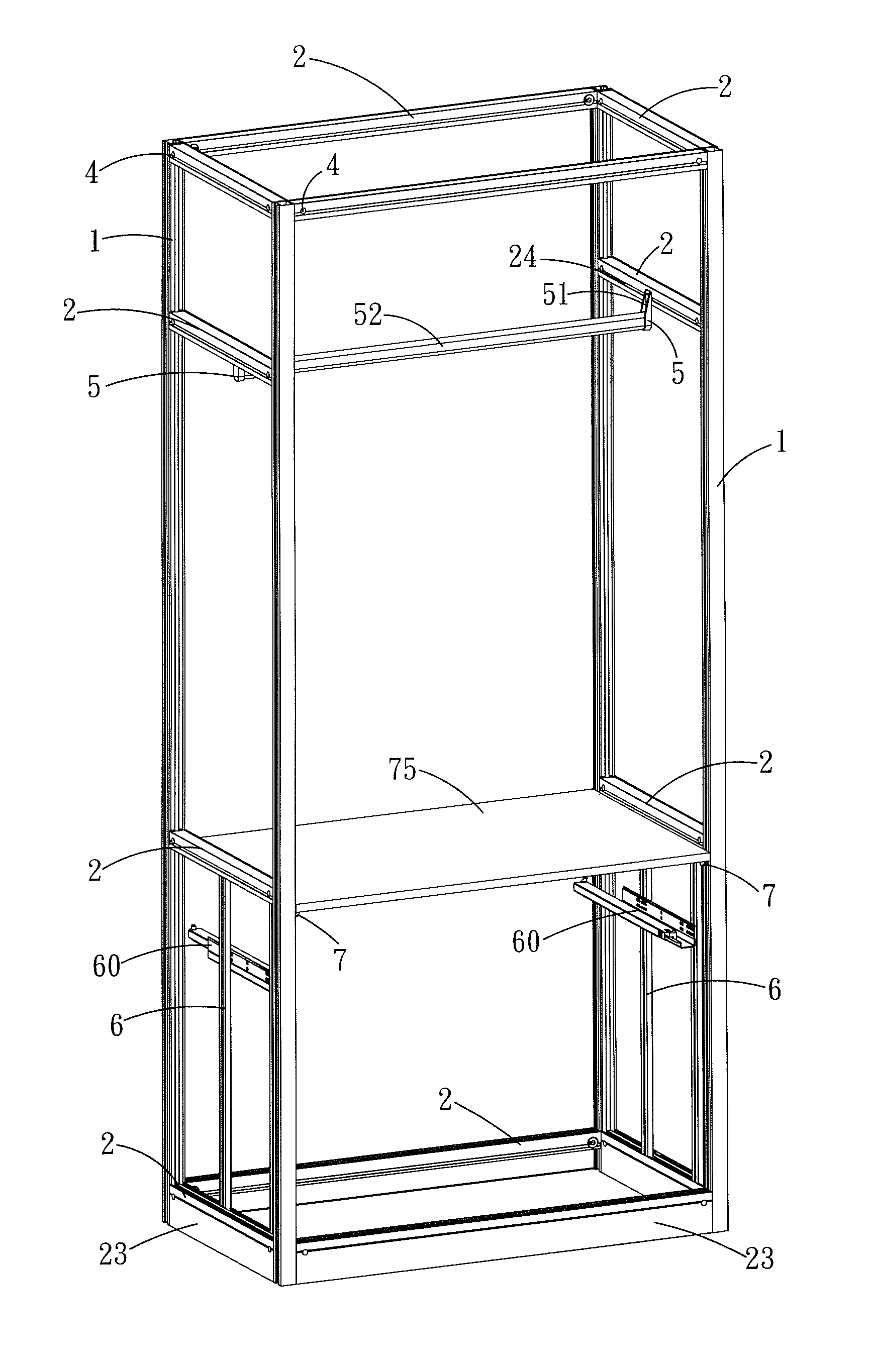
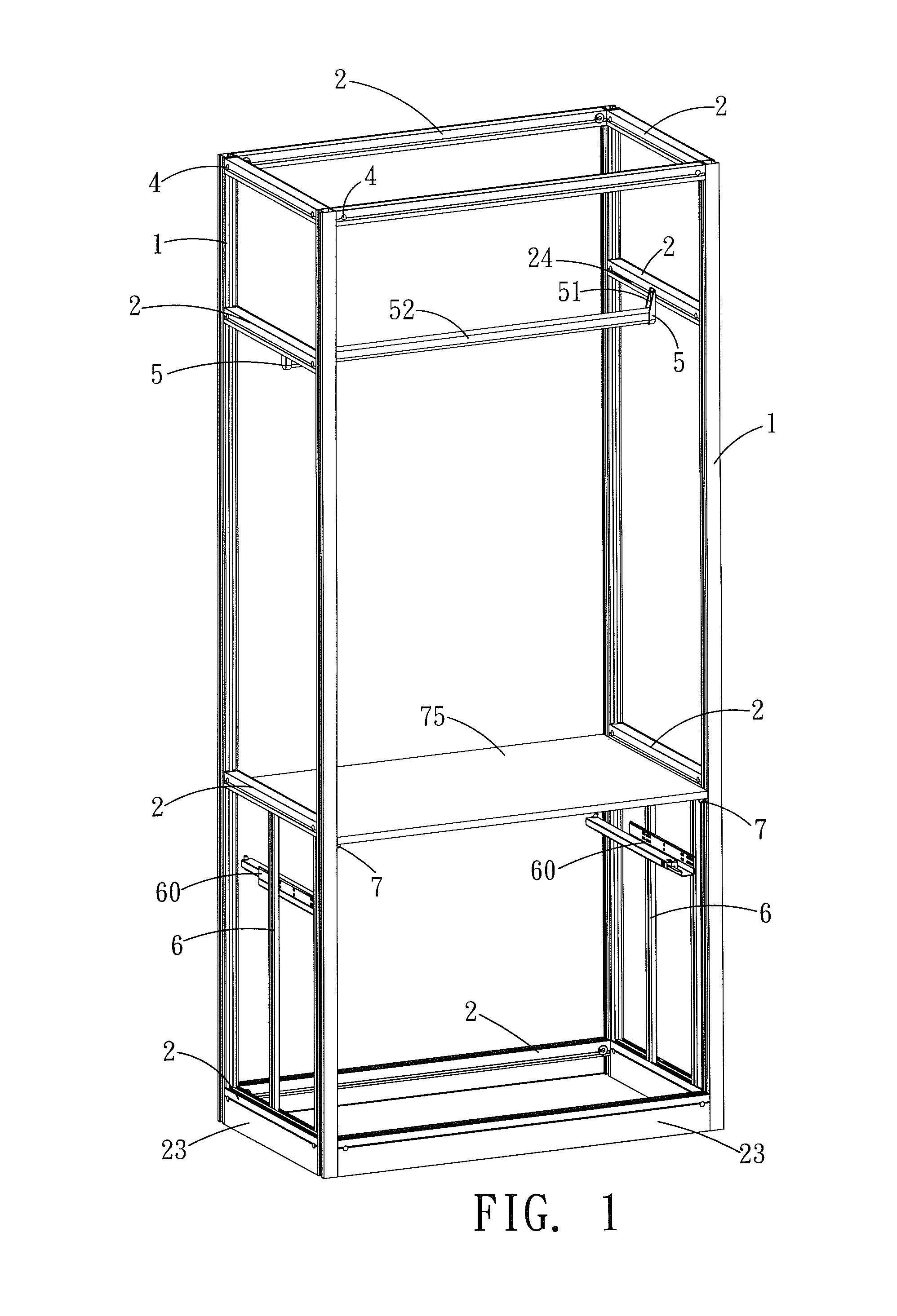
[0030]Referring to the drawings and initially to FIGS. 1-4, a combination cabinet in accordance with the preferred embodiment of the present invention comprises a plurality of upright posts 1, a plurality of crossbars 2 arranged between the upright posts 1, a plurality of connectors 3 mounted between the upright posts 1 and the crossbars 2 to connect the upright posts 1 and the crossbars 2, and a plurality of rotation knobs 4 mounted between the crossbars 2 and the connectors 3.

[0031]Each of the upright posts 1 has a periphery provided with a plurality of guide tracks 10 (see FIGS. 2 and 2a). Each of the guide tracks 10 extends in a longitudinal direction of each of the upright posts 1.

[0032]Each of the crossbars 2 has an interior provided with a mounting hole 20 (see FIGS. 3 and 3a). Each of the crossbars 2 has a surface provided with a passage 21. The passage 21 of each of the crossbars 2 is connected to the mounting hole 20 and has a periphery provided with an entrance 22. Each o...


PUM

PropertyMeasurementUnit
widthaaaaaaaaaa
lengthaaaaaaaaaa
distanceaaaaaaaaaa

Abstract

A combination cabinet includes a plurality of upright posts, a plurality of crossbars arranged between the upright posts, a plurality of connectors mounted between the upright posts and the crossbars to connect the upright posts and the crossbars, and a plurality of rotation knobs mounted between the crossbars and the connectors. Thus, the upright posts and the crossbars are combined together by interaction of the connectors and the rotation knobs. In addition, when the crossbars are unlocked from the upright posts, the crossbars are moved freely relative to the upright posts to adjust the position of the crossbars relative to the upright posts.

Description

BACKGROUND OF THE INVENTION[0001]1. Field of the Invention[0002]The present invention relates to a house furniture and, more particularly, to a combination cabinet.[0003]2. Description of the Related Art[0004]A conventional combination cabinet comprises two side plates, a top plate mounted between the side plates, a bottom plate mounted between the side plates, a drawer mounted between the side plates, and a plurality of separation plates mounted between the side plates and located between the top plate and the bottom plate. However, the conventional combination cabinet has a fixed structure so that the user cannot change and adjust the relative positions of the plates of the conventional combination cabinet according to their practical requirement. In addition, the distance between the separation plates is fixed and cannot be adjusted freely.BRIEF SUMMARY OF THE INVENTION[0005]In accordance with the present invention, there is provided a combination cabinet, comprising a plurality ...

Claims


Application Information

Patent Timeline
Patent Type & Authority Patents(United States)
IPC IPC(8): A47B43/04F16B7/00
CPCA47B47/03F16B7/00A47B43/04A47B47/0083Y10T403/4662F16B7/20Y10T403/39F16B7/0473F16B7/187F16B2200/20
Inventor CHEN, SHUN-TENG
Owner CHEN SHUN TENG
Why Eureka
Try Eureka