Steering system

a steering system and steering shaft technology, applied in the direction of fluid steering, mechanical equipment, transportation and packaging, etc., can solve the problem of gear rattle generation, and achieve the effect of suppressing the generation of gear rattle and improving steering feel

Active Publication Date: 2014-04-29
JTEKT CORP
View PDF24 Cites 14 Cited by
  • Summary
  • Abstract
  • Description
  • Claims
  • Application Information

AI Technical Summary

Benefits of technology

[0011]The invention provides a steering system with which generation of gear rattle is suppressed and the steering feel is improved.

Problems solved by technology

Then, gear rattle is generated when the rack teeth contact the pinion teeth.

Method used


Image

  • Steering system
  • Steering system
  • Steering system

Examples


Embodiment Construction

[0021]Hereinafter, embodiments of the invention will be described with reference to the accompanying drawings.

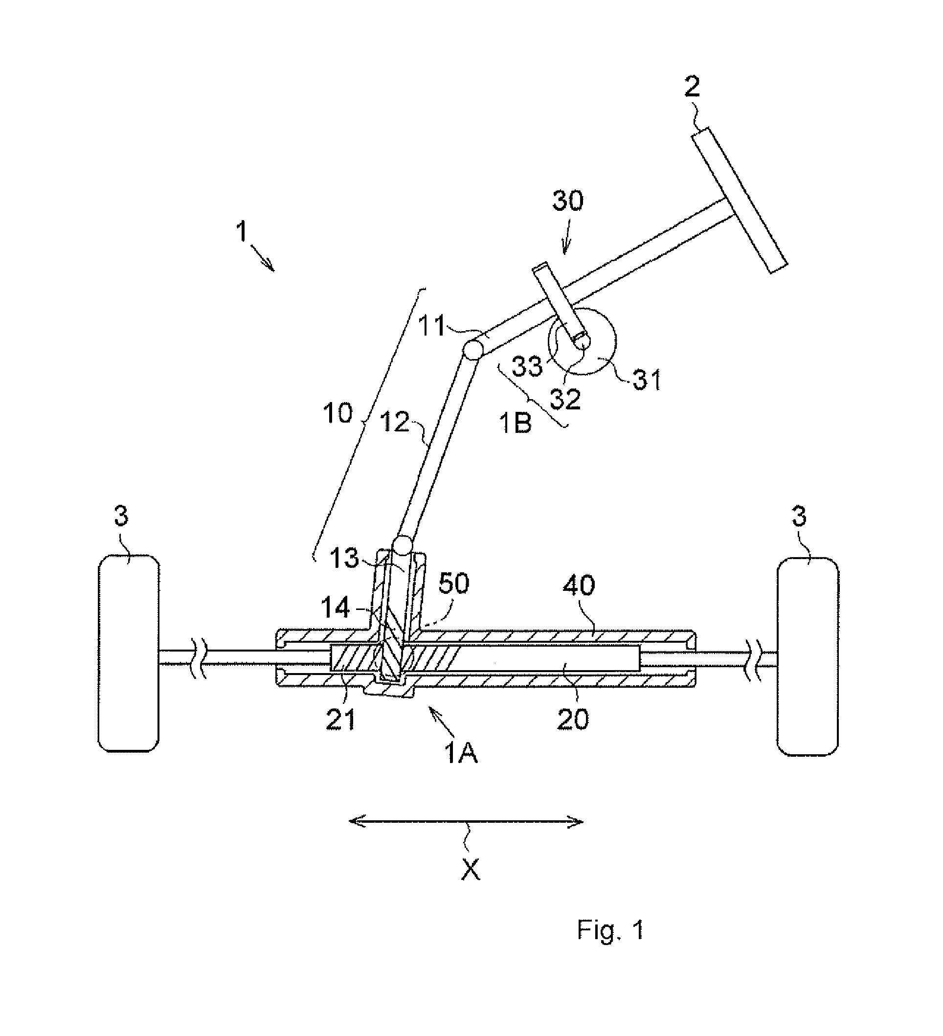
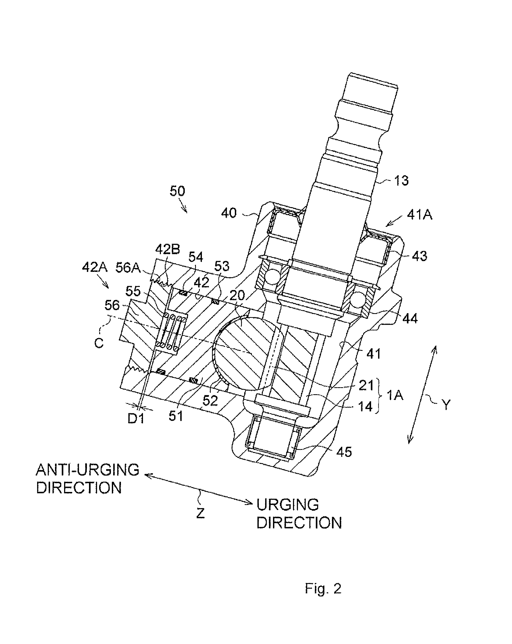
[0022]The configuration of a steering system 1 will be described with reference to FIG. 1. The steering system 1 includes a steering shaft 10, a rack shaft 20, an assist device 30, a housing 40 and a rack guide mechanism 50.

[0023]The steering shaft 10 includes a column shaft 11, an intermediate shaft 12 and a pinion shaft 13. A steering wheel 2 is fixed to the column shaft 11. The column shaft 11 transmits the rotation of the steering wheel 2 to the pinion shaft 13 via the intermediate shaft 12. The intermediate shaft 12 connects the column shaft 11 and the pinion shaft 13 to each other. The pinion shaft 13 has a plurality of pinion teeth 14. The pinion teeth 14 constitute a rack-and-pinion mechanism 1A.

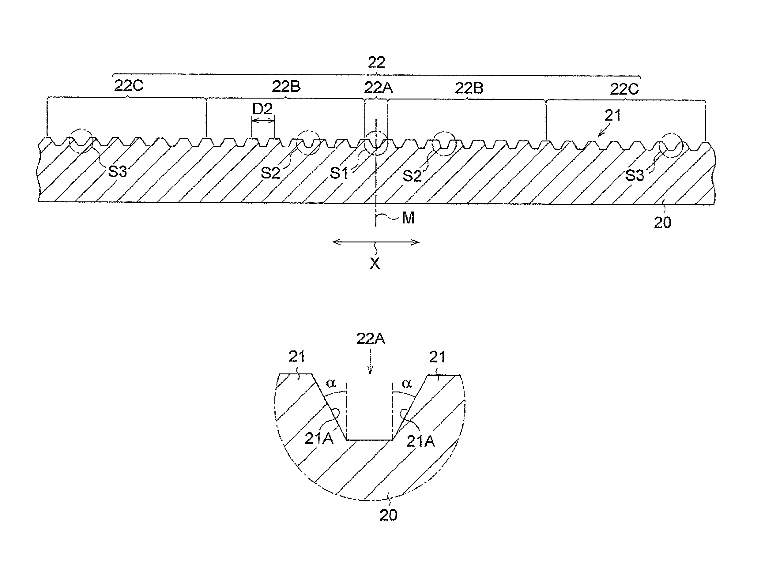
[0024]The rack shaft 20 has a plurality of rack teeth 21. The rack teeth 21 constitute the rack-and-pinion mechanism 1A. Due to meshing of the rack teeth 21 with the pinion t...


PUM


Abstract

A pinion shaft of a steering system has a plurality of pinion teeth. A rack shaft has a stroke region in which a plurality of rack teeth that mesh with the pinion teeth is formed. The stroke region includes a center region that includes a center position of the stroke region, end regions, each of which includes an end position of the stroke region, and intermediate regions, each of which is located between the center region and one of the end regions. A pressure angle of each rack tooth included in each of the intermediate regions is smaller than a pressure angle of each rack tooth included in each of the center region and the end regions.

Description

INCORPORATION BY REFERENCE / RELATED APPLICATION[0001]This application claims priority to Japanese Patent Application No. 2012-051890 filed on Mar. 8, 2012 the disclosure of which, including the specification, drawings and abstract, is incorporated herein by reference in its entirety.BACKGROUND OF THE INVENTION[0002]1. Field of the Invention[0003]The invention relates to a steering system that includes a pinion shaft, a rack shaft and a support yoke.[0004]2. Discussion of Background[0005]A rack-and-pinion steering system includes a pinion shaft, a rack shaft and a rack guide mechanism. The pinion shaft has a plurality of pinion teeth. The rack shaft has a plurality of rack teeth. US 2008 / 0223163 A1 describes a steering system that includes a pinion shaft and a rack shaft,[0006]The rack guide mechanism includes a support yoke, an urging member and a restricting member. The support yoke guides movement of the rack shaft. The urging member applies, to the support yoke, a force that acts ...

Claims


Application Information

Patent Timeline
Patent Type & Authority Patents(United States)
IPC IPC(8): B62D3/12B62D5/22
CPCF16H55/28B62D3/123B62D3/12B62D3/126B62D5/22
Inventor SUMIHARA, HIDETOSHI
Owner JTEKT CORP
Why Eureka
Try Eureka