Circuitry for measuring and compensating phase and amplitude differences in NDT/NDI operation

a phase and amplitude difference technology, applied in the direction of noise figure or signal-to-noise ratio measurement, instruments, machines/engines, etc., can solve the problems of large inspection errors, high noise levels, and amplitude and phase of responding signals often shifting from their original detection ones, so as to reduce manufacturing costs, reduce noise ratios, and reduce the development cycle

Active Publication Date: 2014-04-29
OLYMPUS AMERICA
View PDF1 Cites 3 Cited by
  • Summary
  • Abstract
  • Description
  • Claims
  • Application Information

AI Technical Summary

Benefits of technology

[0015]Accordingly, it is a general object of the present disclosure to provide a method and an NDT / NDI inspection device capable of detecting phase and amplitude differences of an electrical or acoustical signal with desirable accuracy without causing excessive noise and temperature drift.
[0019]It is further an object of the present disclosure to provide a method and circuitry capable of providing near infinite compensation of phase and amplitude difference in the transducer and circuit.
[0020]It can be understood that the presently disclosed method and circuitry provide the advantages of providing infinite compensation of phase and amplitude difference without using a large number of electronic (analog) components.
[0021]It also should be appreciated that the presently disclosed circuitry provides the advantanges of lower development cycle and reduced manufacturing cost.
[0022]In addition, an alternative embodiment of the presently disclosed probe provides the advantage of achieving lower signal to noise ratios and lower temperature drift effects which are desirable characteristics for NDT / NDI devices to possess.

Problems solved by technology

However, the amplitude and phase of the responding signals often shift from their original detecting ones due to reasons that are not associated with the defects or thickness of the test objects.
The mostly analog methods require many analog components which can induce higher noise levels and have higher temperature drift effects in the test system thereby creating larger errors in the inspection results.
Another typical problem associated with mostly analog versus digital methods of phase and amplitude detection is that it requires multiple components thereby increasing the cost of the inspection or measurement system and requiring a larger amount of printed circuit board area making the inspection or measurement system larger while digital methods can be compacted into a single field programmable gate array (FPGA), CPLD or other programmable digital device.
Returning to the problem at issue, '843 does not provide a solution for detection of phase and amplitude differences.
The same inventor teaches in U.S. Pat. No. 6,850,077 a solution to a problem similar to that of the '843 patent and therefore does not provide a solution to the problem of the present disclosure.

Method used


Image

  • Circuitry for measuring and compensating phase and amplitude differences in NDT/NDI operation
  • Circuitry for measuring and compensating phase and amplitude differences in NDT/NDI operation
  • Circuitry for measuring and compensating phase and amplitude differences in NDT/NDI operation

Examples


Embodiment Construction

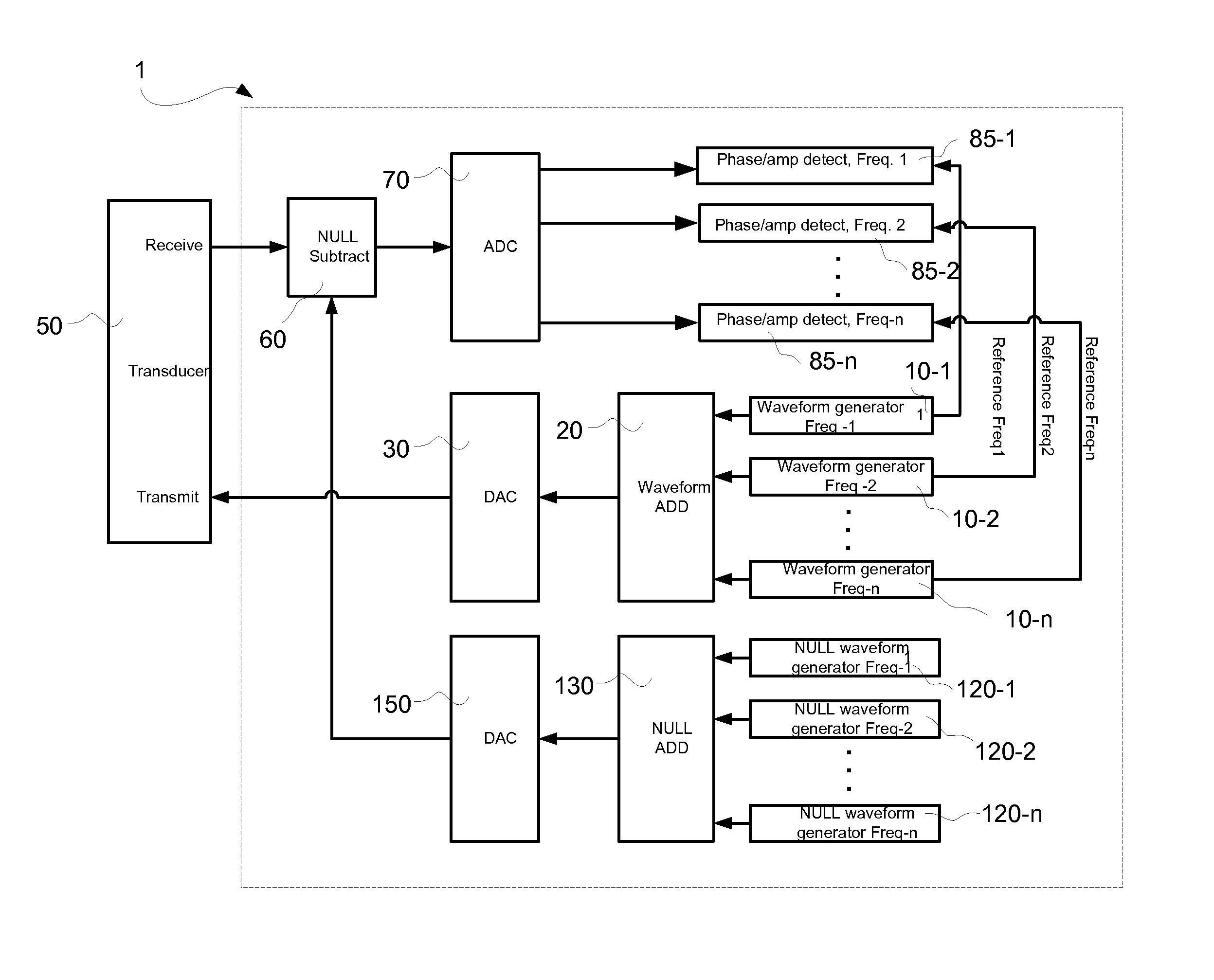
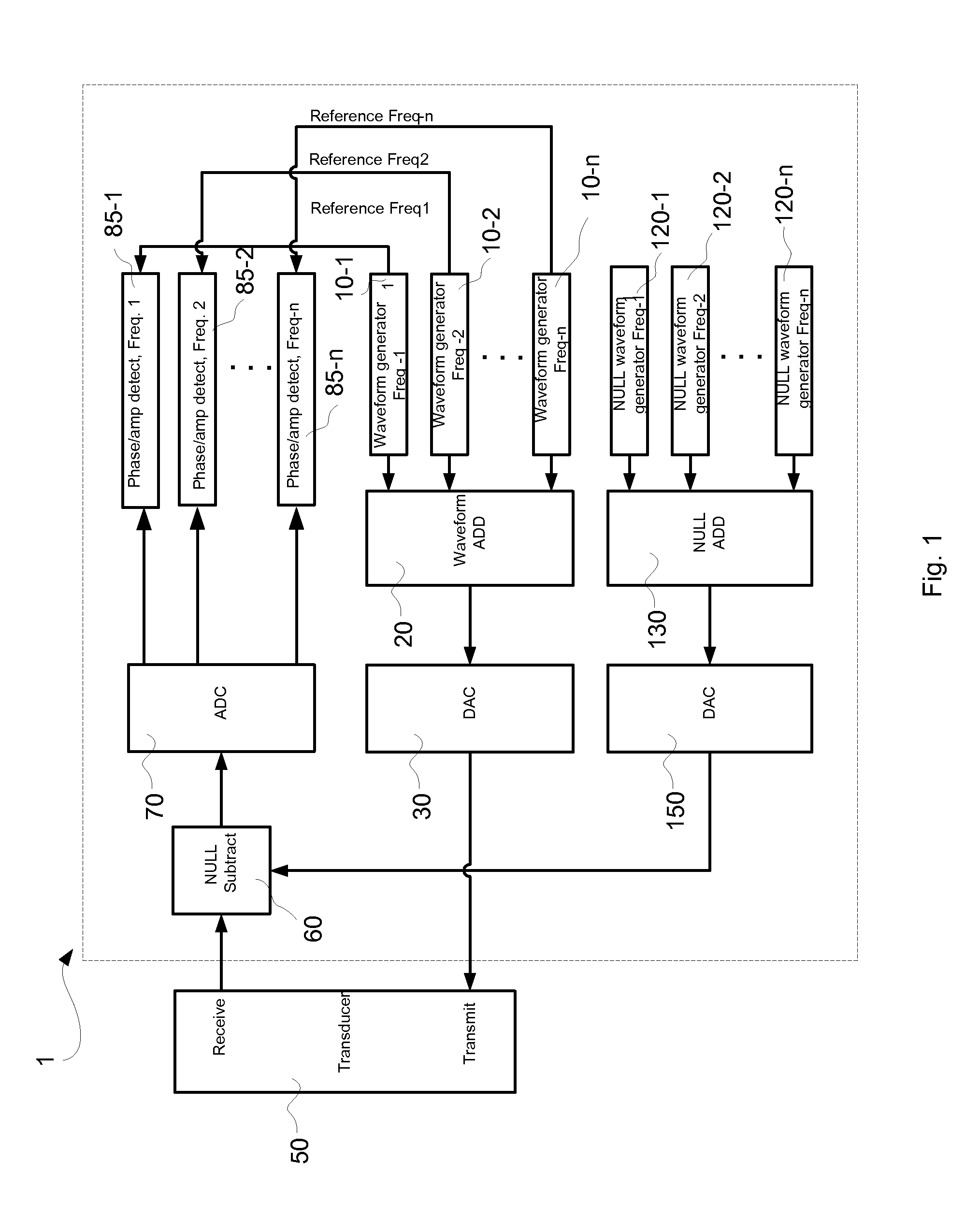
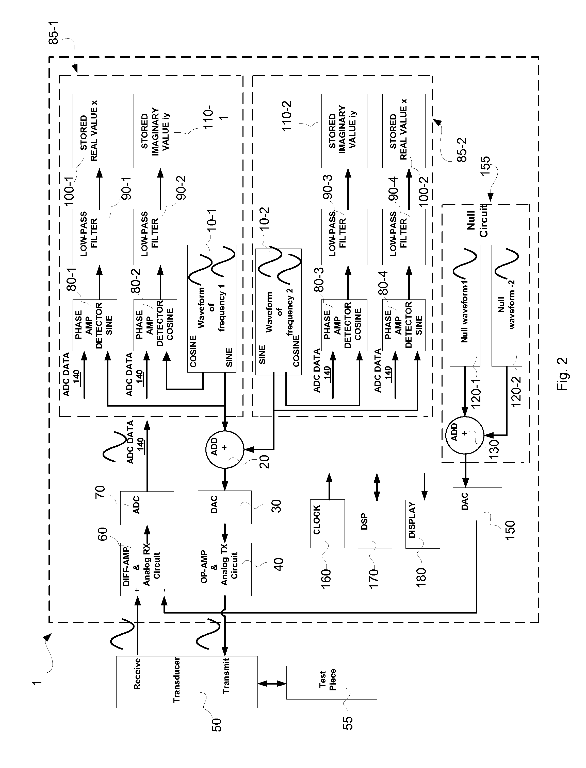
[0028]The measurement of phase and amplitude is continuously monitored for differences between responding signals and transmit (detecting) signals by continuously injecting a transmit signal into the test piece and monitoring the responding signal from the test piece. A herein disclosed null compensation is done once during a calibration session before measurement with the transducer un-coupled from the test piece, to compensate for phase and amplitude differences caused by system and test piece's intrinsic properties such as the transducer and electrical circuitry.

[0029]It should be noted that when referring to numerals of items in the figures, a numeral without a post-suffix is meant to denote all items in the figure that bear the same numeral with a post suffix. For example, digital waveform generator 10 shown in FIGS. 1 and 2 is meant to denote all and each waveform generator of the same kind, namely 10-1, 10-2, and so on.

[0030]It should be noted that the present disclosure pres...


PUM


Abstract

Disclosed are a method and an NDT / NDI inspection device deploying digital circuitry to conduct detection and compensation of phase and amplitude shift in responding signals. A digital waveform generator, such as a direct digital synthesizer (DDS) is used to generate a digital sine-wave of a specific frequency and amplitude, mimicking the pulser frequency and amplitude. The sine-wave is converted to analog signal through a DAC and transmitted to the transducer. The received analog sine-wave from the transducer is converted back to a digital signal through an ADC. The transmitted and received digital signals are then compared for phase and amplitude differences. A null circuit involving another waveform generating component is employed to compensate the detected phase and amplitude differences. As a result the phase and amplitude differences are effectively eliminated before being further processed and analyzed for defects information.

Description

FIELD OF THE INVENTION[0001]The present invention relates to non-destructive testing and inspection devices (NDT / NDI) and more particularly to an NDT / NDI device with improved phase and amplitude measurement and compensation using a digital circuit.BACKGROUND OF THE INVENTION[0002]During NDT / NDI operations, detecting or transmitting signals are sent into targeted test objects. Responding signals are received by the instrument or system of the NDT / NDI operation, back from the test objects. In many applications, the characteristics of the detecting signals involve amplitude and phase. However, the amplitude and phase of the responding signals often shift from their original detecting ones due to reasons that are not associated with the defects or thickness of the test objects. The shift in the responding signal's amplitude and phase in comparison to those of the original detecting signals can be attributed to factors including certain intrinsic properties of the circuitry of the probes...

Claims


Application Information

Patent Timeline
Patent Type & Authority Patents(United States)
IPC IPC(8): G06F19/00
CPCG01N29/32G01N29/4436G01N29/36
Inventor THOMAS, ANDREWDULAC, MARC
Owner OLYMPUS AMERICA
Why Eureka
Try Eureka