Operation Support System, Vehicle, And Method For Estimating Three-Dimensional Object Area

a technology of three-dimensional object area and support system, which is applied in the field of operation support system, can solve the problems of troublesome introduction of technique, high cost, and high probability of collision accidents in the blind spots of drivers, and achieve the effect of desirable accuracy

Inactive Publication Date: 2010-09-30
SANYO ELECTRIC CO LTD
View PDF3 Cites 50 Cited by
  • Summary
  • Abstract
  • Description
  • Claims
  • Application Information

AI Technical Summary

Benefits of technology

[0019]According to the present invention, it is possible to estimate a three-dimensional object area with desirable accuracy based on an image obtained from a camera.
[0020]The significance and benefits of the invention will be clear from the following description of its embodiments. It should however be understood that these embodiments are merely examples of how the invention is implemented, and that the meanings of the terms used to describe the invention and its features are not limited to the specific ones in which they are used in the description of the embodiments.

Problems solved by technology

A three-dimensional object standing on a road surface can be an obstacle to a vehicle, and driver's overlooking it may lead to a collision accident.
Such collision accidents are particularly likely to occur in the blind spots of drivers.
However, use of a stereo camera itself, which is composed of two cameras, invites a cost increase.
Also, the positions and angles of the two cameras need to be adjusted with high accuracy, and this makes it troublesome to introduce the technique.

Method used


Image

  • Operation Support System, Vehicle, And Method For Estimating Three-Dimensional Object Area
  • Operation Support System, Vehicle, And Method For Estimating Three-Dimensional Object Area
  • Operation Support System, Vehicle, And Method For Estimating Three-Dimensional Object Area

Examples


example 1

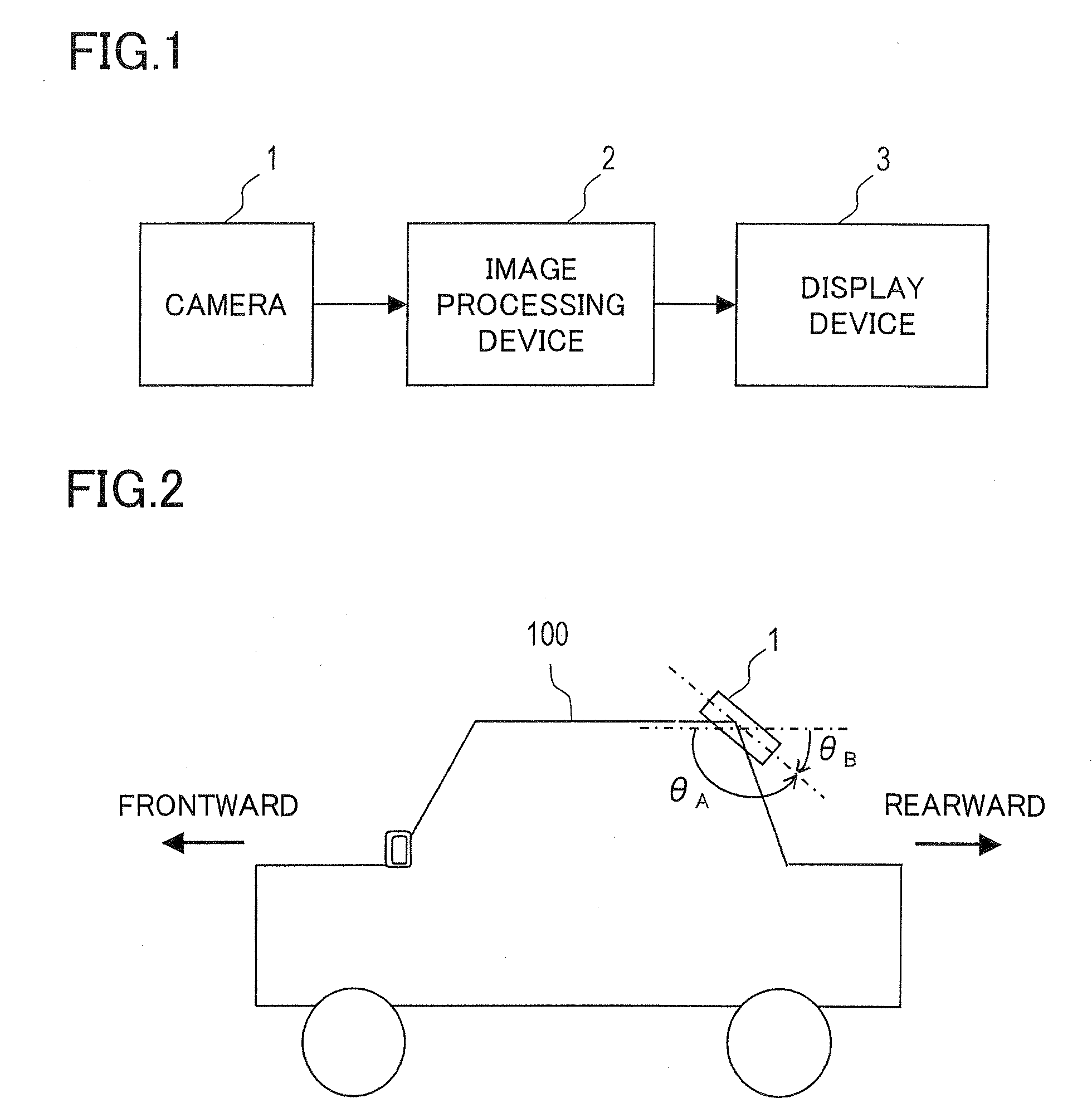
[0069]First, Example 1 will be described. The image processing device 2 shown in FIG. 1 acquires camera images at a predetermined cycle from the camera 1, generates display images one after another from the camera images thus acquired one after another, and keeps outputting the latest display image to the display device 3. Thereby, the display device 3 displays the latest display image in a constantly updated fashion.

[0070]The image processing device 2 is provided with a function of estimating a three-dimensional object area within an image. A three-dimensional object area denotes an area in which a three-dimensional object appears. A three-dimensional object is an object with height, such as a person. Any object without height, such as a road surface forming the ground, is not a three-dimensional object. A three-dimensional object can be an obstacle to the traveling of the vehicle 100.

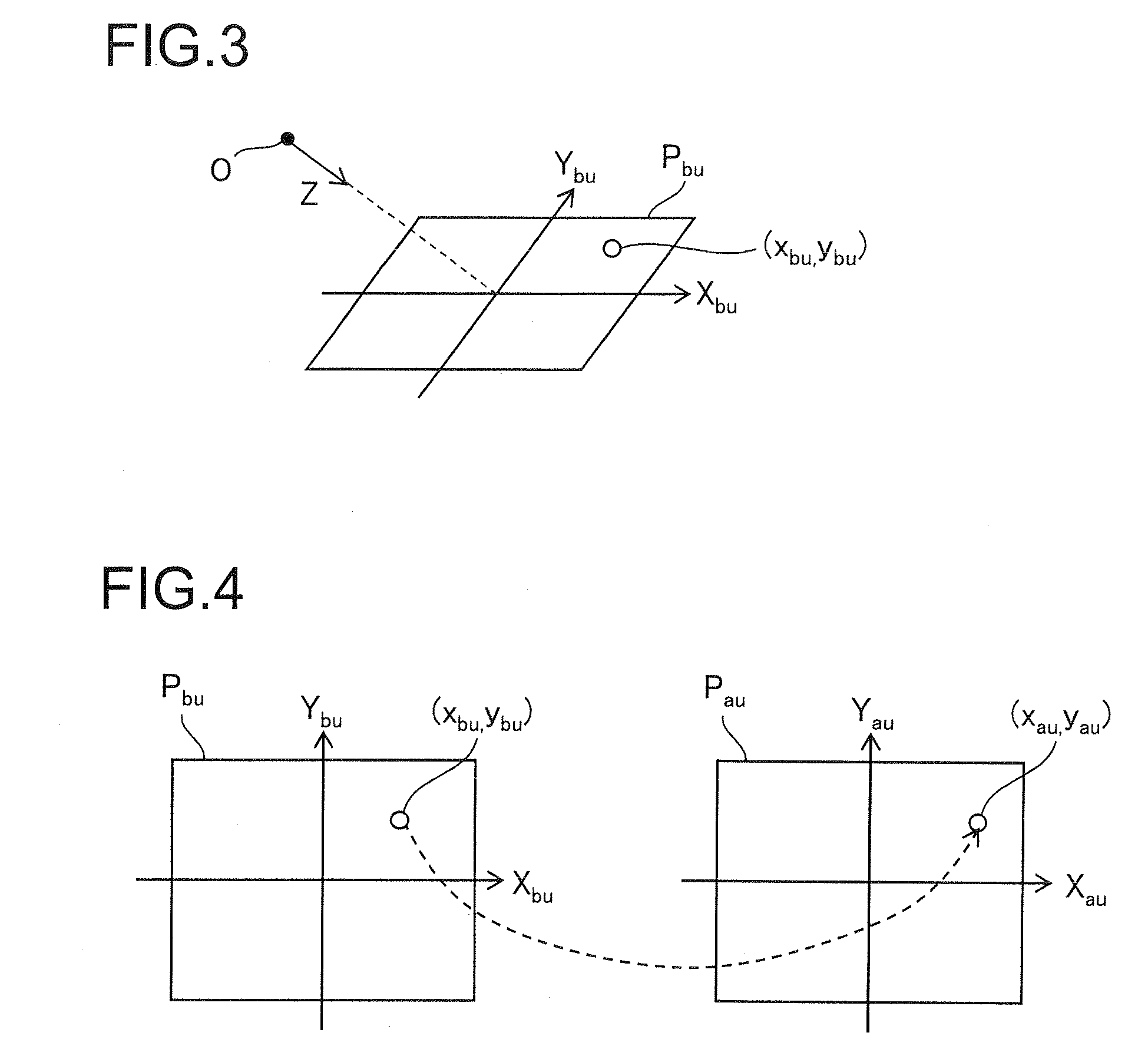
[0071]In bird's eye conversion, coordinate conversion is so performed that a bird's eye view age h...

example 2

[0116]Example 2 will be described next. In Example 1, the differential image DI is generated by obtaining the difference in pixel value between the reference image TS1 and the bird's eye view image TI2 with respect to each pixel. This method, however, is prone to be negatively affected by local noise. In Example 2, a differential image generating method and a three-dimensional object area estimation method less prone to be negatively affected by local noise will be discussed. Example 2 corresponds to an example resulting from partially modifying Example 1, and, unless inconsistent, any feature in Example 1 is applicable to Example 2. The operation performed until the bird's eye view images TI1 and TI2 and the reference image TS1 are obtained via the processing in steps S11 to S17 and part of the processing in step S18 in FIG. 5 is performed in the same manner as in Example 1, and thus the description will be focused on what is done after the operation.

[0117]In Example 2, the bird's ...

example 3

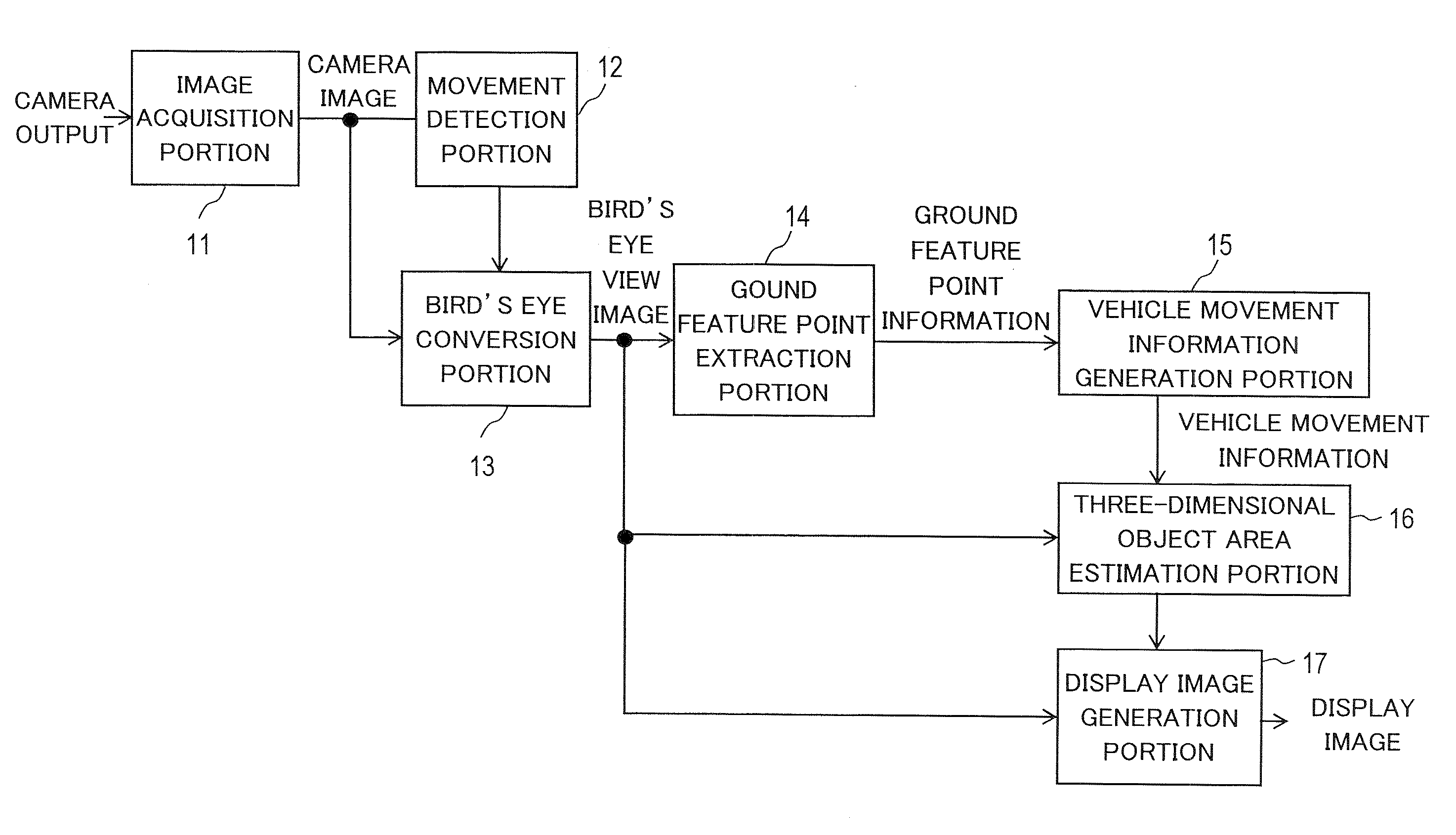
[0137]Next, example 3 will be described. In Example 3, a description will be given of an example of a functional block diagram of an operation support system corresponding to the practical examples described above. FIG. 25 is a functional block diagram of an operation support system according to Example 3. The operation support system according to Example 3 includes blocks referred to by the reference signs 11 to 17, and these blocks referred to by the reference signs 11 to 17 are provided in the image processing device 2 in FIG. 1.

[0138]An image acquisition portion 11 acquires one camera image after another based on an output signal of the camera 1. The image data of each camera image is fed from the image acquisition portion 11 to a movement detection portion (movement vector detection portion) 12 and to a bird's eye conversion portion 13. The movement detection portion 12 executes processing of step S12 and processing of step S13 shown in FIG. 5. That is, the movement detection p...


PUM


Abstract

Camera images at times (t1 and t2) are acquired from a camera installed on a vehicle, and the camera images are converted to bird's-eye view images at the times (t1 and t2). A plurality of feature points are extracted from the camera image at the time (t1) and the movement vectors of the respective feature points between first and second camera images are detected. Then, the respective feature points and the respective movement vectors are mapped onto a bird's-eye image coordinate plane. Two or more feature points on the bird's-eye view images are permitted to be targets, the positions and the movement vectors of the target feature points are applied to an equation of constraint which ground surface feature points have to satisfy, thereby discriminating whether the target feature points are the ground surface feature points. Then, from position information and movement vector information on the two or more feature points discriminated to be the ground surface feature points, movement information on the vehicle is obtained and used for taking the difference between the bird's-eye images at the times (t1 and t2) to estimate a three-dimensional object area.

Description

TECHNICAL FIELD[0001]The present invention relates to an operation support system. In particular, the present invention relates to a technology for estimating, from a result of shooting by a camera fitted to a mobile object, a three-dimensional object area, i.e. an area where a three-dimensional object appears. The present invention also relates to a vehicle employing such an operation support system.BACKGROUND ART[0002]A three-dimensional object standing on a road surface can be an obstacle to a vehicle, and driver's overlooking it may lead to a collision accident. Such collision accidents are particularly likely to occur in the blind spots of drivers. Thus there has been proposed a technique according to which a vehicle is fitted with a camera for monitoring areas that tend to be the driver's blind spots so that an image obtained from the camera is displayed on a display device disposed near the driver's seat. There has also been developed a technology for converting a camera imag...

Claims


Application Information

Patent Timeline
Patent Type & Authority Applications(United States)
IPC IPC(8): G06K9/00
CPCB60R1/00B60R2300/105B60R2300/303B60R2300/307G06T2207/10016B60R2300/8033B60R2300/8093G06T7/2033B60R2300/607G06T7/246
Inventor YANG, CHANGHUI
Owner SANYO ELECTRIC CO LTD
Why Eureka
Try Eureka