Lighting device

a technology for outdoor lighting and lighting devices, which is applied in the direction of semiconductor devices for light sources, lighting and heating equipment, fixed installations, etc., can solve the problems of large amount of electric power consumption, and achieve the effect of simple structure, effective use and compact siz

Active Publication Date: 2014-05-06
NICHIA CORP +1
View PDF11 Cites 21 Cited by
  • Summary
  • Abstract
  • Description
  • Claims
  • Application Information

AI Technical Summary

Benefits of technology

[0023]The lighting device according to the present invention can obtain the following advantageous effects:
[0024](1) The structure of the lighting device can be simplified and compact in size, and the lighting device can make effective use of the light emitted by the semiconductor light source by means of the first lens section having the curvature surface unit and the second lens section having the lens plate for distributing light to an area to be lighted such as a road surface;
[0025](2) The operation of the lighting device is facilitated since the lighting device includes the first lens section having the curvature surface unit and the prisms, and includes the lens plate having the second lens section; therefore, it is not necessary to adjust the installation angle of the lighting device. In particular, the lighting device can effectively adjust the direction of light emitted by the semiconductor light source in the vicinity of the semiconductor light source, and the lighting device can distribute light to an area to be lighted in a balanced manner without forming a secondary peak regardless of the position of installing the lighting device; and
[0026](3) The lighting device can distribute light to an area to be lighted in a balanced manner without forming a secondary peak regardless of the position of the lighting device installed relative to the area to be lighted since, in the lighting device, the unit center axis of the curvature surface unit is shifted from the center light axis of the semiconductor light source, therefore, the light emitted by the semiconductor light source toward underneath the semiconductor light source can be directed smoothly.

Problems solved by technology

However, these types of lighting device consume a great amount of electric power; therefore, an environmentally friendly energy saving lighting device has been sought after in recent years.

Method used


Image

  • Lighting device
  • Lighting device
  • Lighting device

Examples


Embodiment Construction

[0036]The lighting device according to the present invention will be explained as follows with reference to the accompanying drawings.

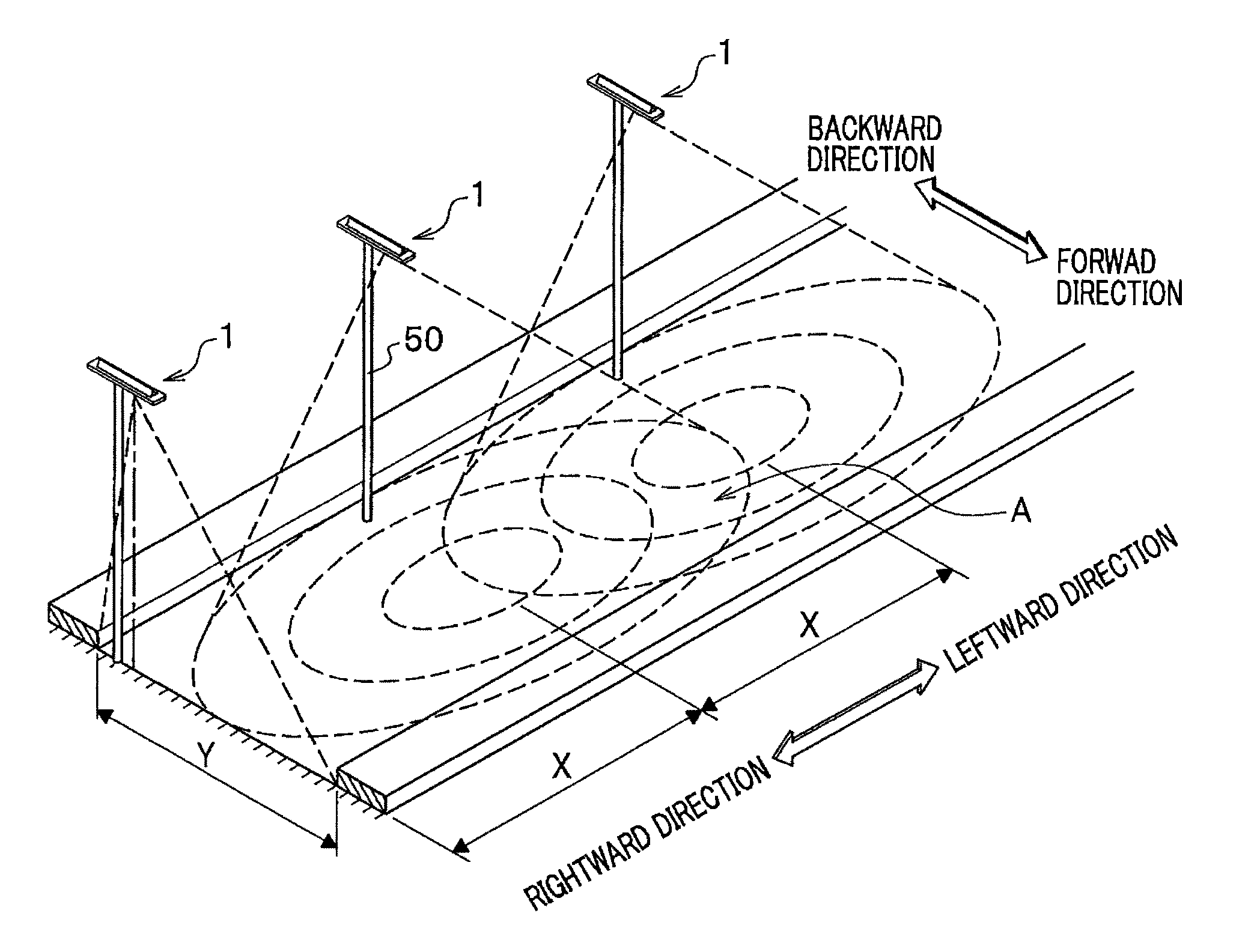
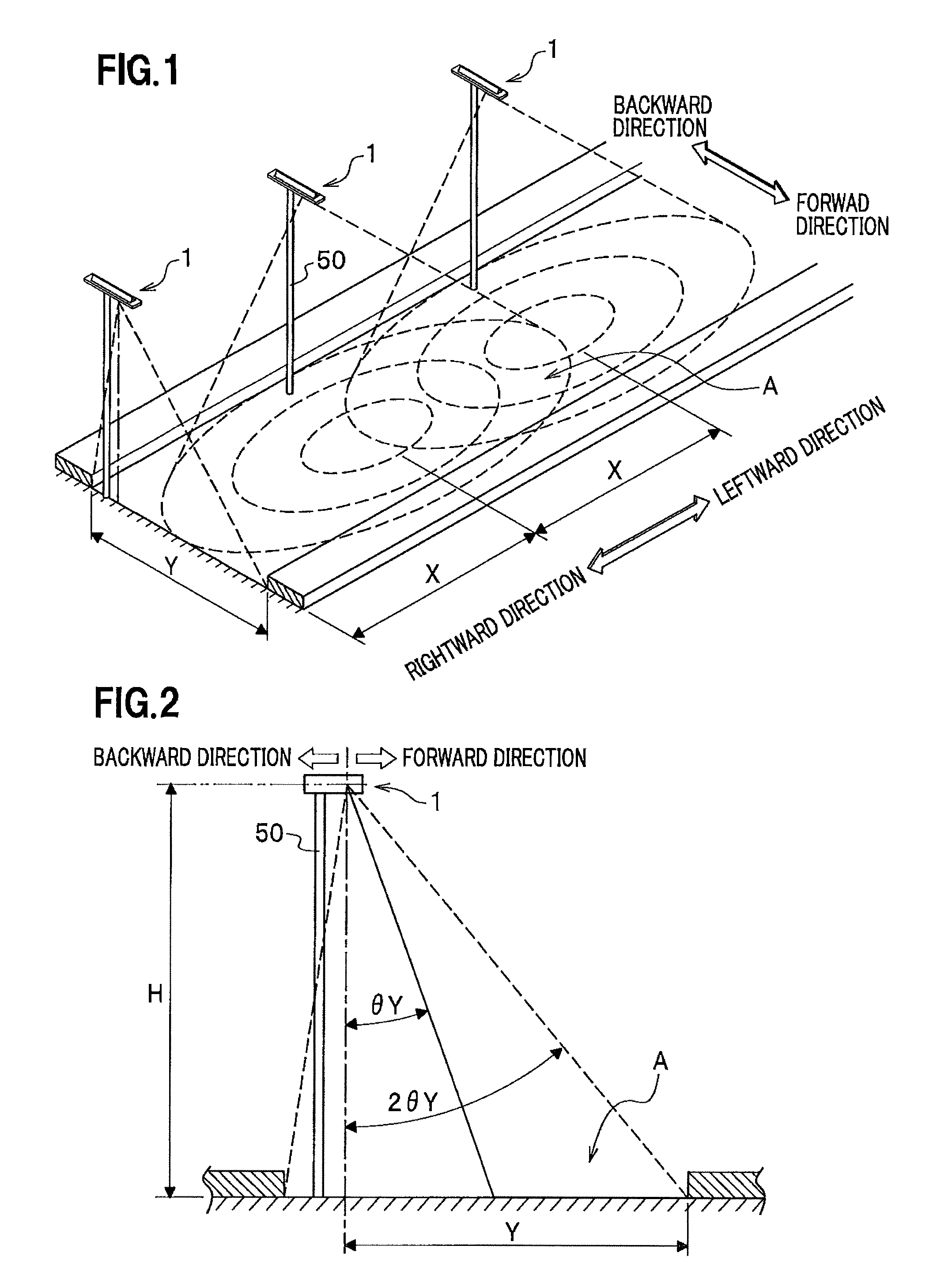
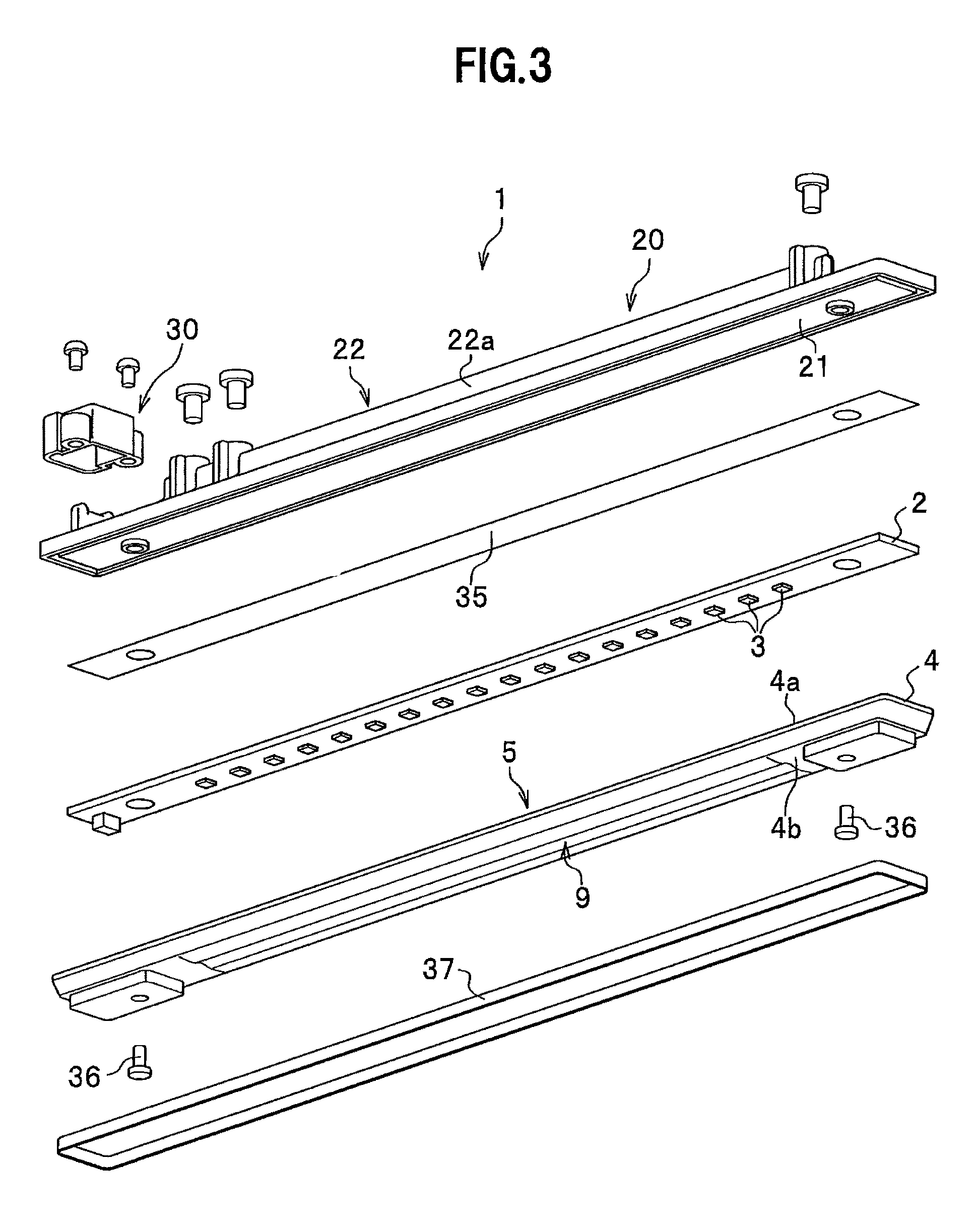
[0037]FIG. 1 is a perspective view schematically showing an installed state of the lighting device. FIG. 2 is a side view schematically showing an installed state of the lighting device. FIG. 3 is an exploded perspective view of the lighting device. FIGS. 4A to 4C show a lens according to the present invention. FIG. 4A is a perspective view showing the lens cut in part and viewed upward. FIG. 4B is a perspective view showing the lens cut in part and viewed downward. FIG. 4C is an enlarged perspective view showing an area B shown in FIG. 4B. FIG. 5 is a cross sectional view schematically showing the lens plate of the lighting device cut in the longitudinal direction according to the present invention. FIG. 6 is a cross sectional view schematically showing the lens of the lighting device cut orthogonally to the longitudinal direction according to the pr...


PUM


Abstract

A lighting device (1) is configured to include: an elongated flat substrate (2); a plurality of semiconductor light sources (3) arranged on the flat substrate in a longitudinal direction of the flat substrate; and a lens plate (4) disposed to face the semiconductor light sources, wherein the lens plate includes a lens-light-incident surface facing the semiconductor light sources and includes a lens-light-emitting surface, a first lens section (5) is formed on one of the lens-light-incident surface and the lens-light-emitting surface and distributing the light emitted by the semiconductor light source in the longitudinal direction, a second lens section (9) is formed on the other one of the lens-light-incident surface and the lens-light-emitting surface for distributing the light emitted by the semiconductor light sources in a width direction, and the first lens section has a curvature surface unit including two or more convex section curvature surfaces having different curvature radii and formed adjacent in the longitudinal direction, each convex section's curvature surface is disposed inside a facing area facing an area corresponding to a width of each semiconductor light source in the longitudinal direction.

Description

TECHNICAL FIELD[0001]The present invention relates to an outdoor lighting device which uses a semiconductor light source, typically an LED and which is used as a street light, or a crime prevention light etc.BACKGROUND ART[0002]Conventionally, incandescent lamps, fluorescent lights, or mercury lamps are used as an outdoor lighting device installed along streets or in parks etc. However, these types of lighting device consume a great amount of electric power; therefore, an environmentally friendly energy saving lighting device has been sought after in recent years.[0003]To address this, an outdoor lighting device has been proposed in which a plurality of white light-emitting diodes are arranged, which consume much less electric power. In this type of the outdoor lighting device, for example, white light-emitting diodes are disposed on a light-source-mounting surface having a staircase pattern in order to scatter light emitted from the white light-emitting diodes from front to back an...

Claims


Application Information

Patent Timeline
Patent Type & Authority Patents(United States)
IPC IPC(8): F21V7/09
CPCF21S8/08F21S4/003F21V5/04F21W2131/103F21Y2101/02F21Y2103/003F21S2/00F21V5/007F21V5/08F21S4/20F21Y2103/10F21Y2115/10
Inventor KATO, MASARUWATANABE, KAZUNORI
Owner NICHIA CORP
Why Eureka
Try Eureka