
Pass-through vacuum

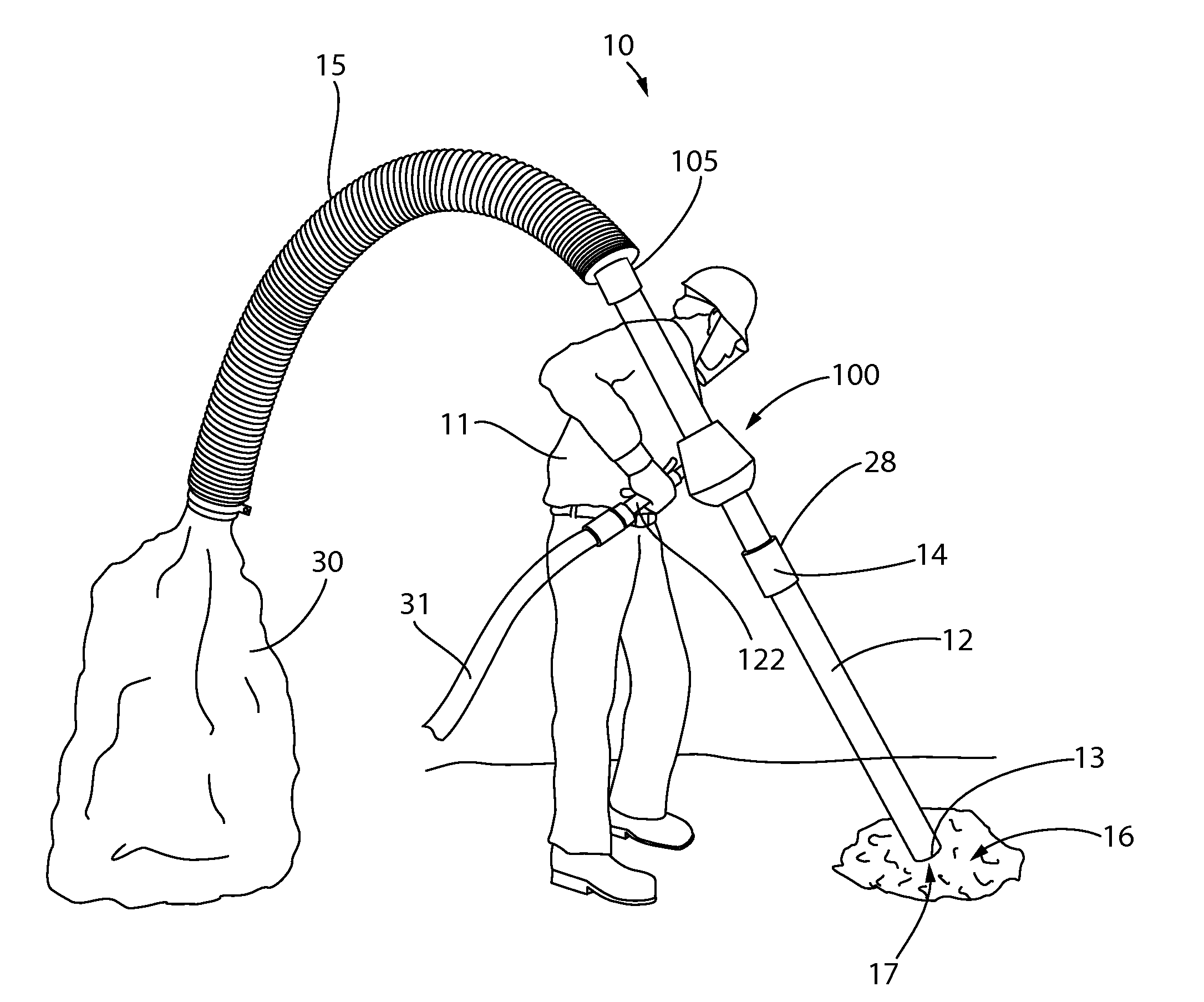
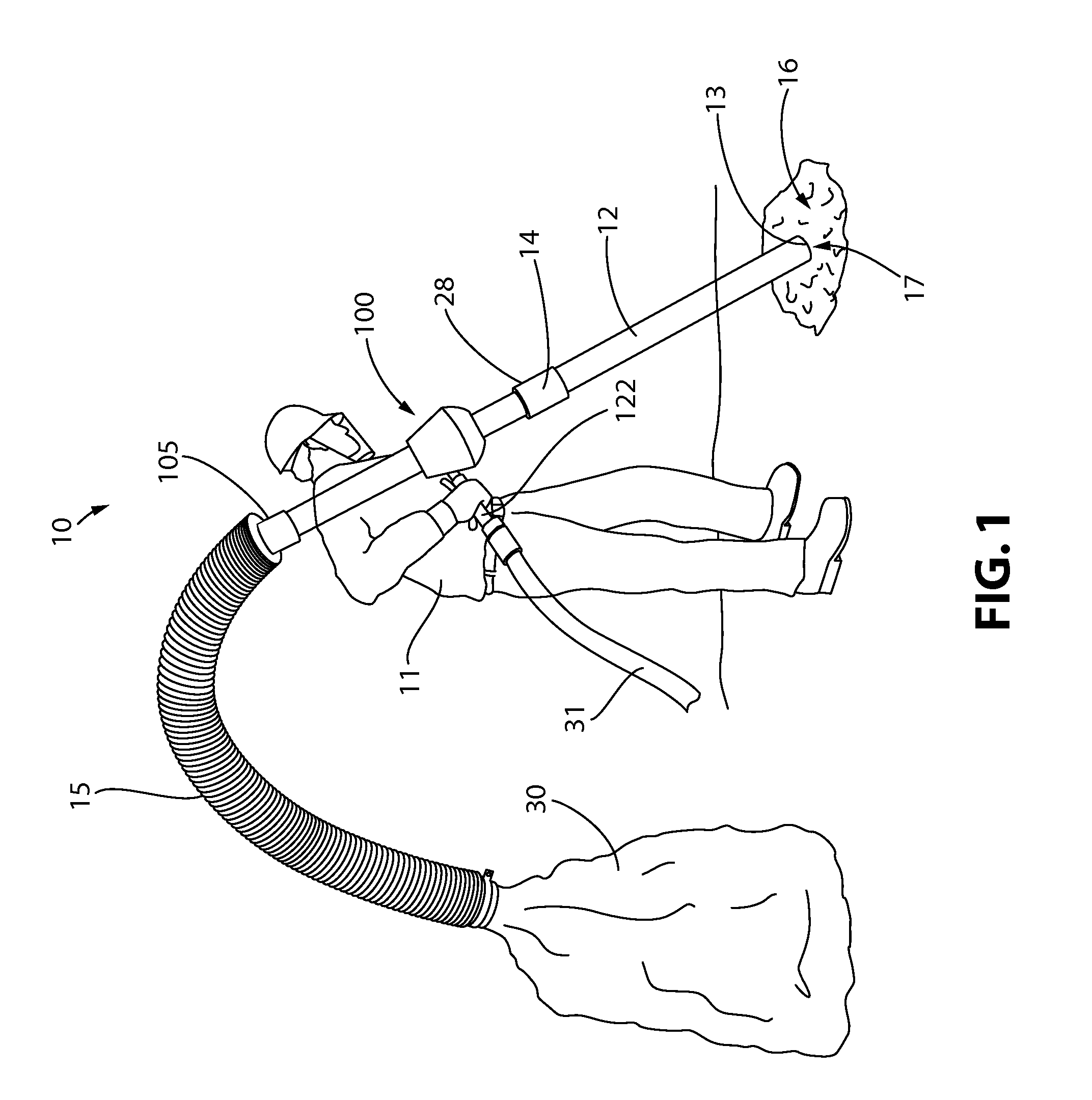
a vacuum and pass-through technology, applied in the direction of soil shifting machines/dredgers, mechanical machines/dredgers, cleaning equipment, etc., can solve the problems of inconvenient material transportation, inconvenient use of low heads, and many prior art systems with disadvantages, etc., to achieve improved efficiency, lower cost, and improved pass-through vacuum

Active Publication Date: 2014-05-13
GUARDAIR CORP
View PDF13 Cites 14 Cited by
  • Summary
  • Abstract
  • Description
  • Claims
  • Application Information

AI Technical Summary

Benefits of technology

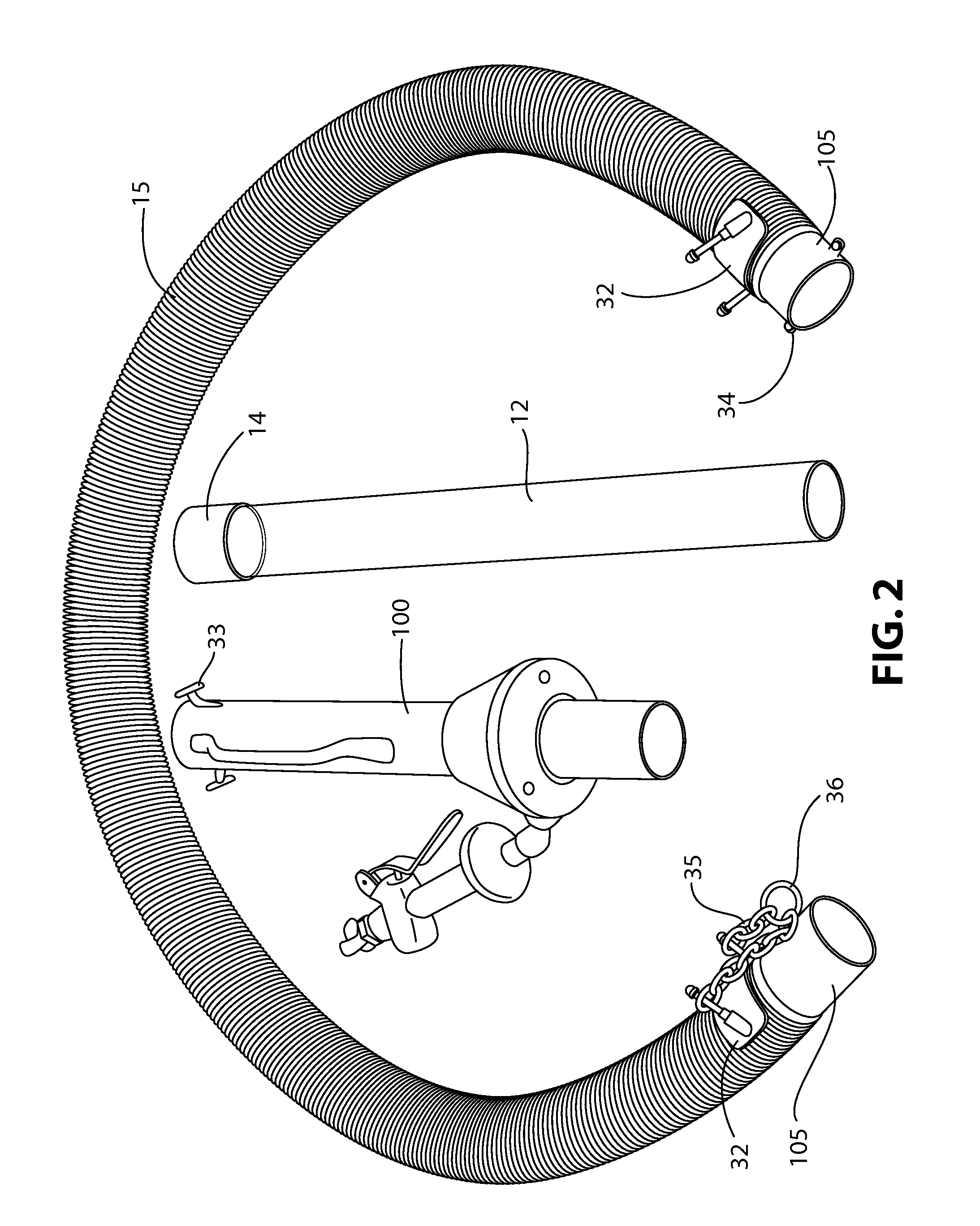
The patent is about a new vacuum device that improves on existing technology. It offers flexibility in construction to easily change the tube for different materials and to match different application needs. The vacuum can also be customized with supersonic air jets to enhance performance. The device has separate parts for the manifold and nozzles, allowing for optimal weight, cost, and wear resistance. It has handles for easy use and may be made of stainless steel or brass for durability. The patent also mentions the use of a label to indicate the requirements and cautions for using the vacuum.

Problems solved by technology

However, many prior art systems have disadvantages as well.
Inefficient means may also be used to convert the energy of the input compressed air into vacuum head to move the material.
However, these generally are for moving high volumes of air and, as such, produce low heads not suitable for moving difficult to convey materials like excavated soil.
This causes a great deal of wear on the injection unit since flowable material conveyed through the injection unit by the entrained gas flow will continually pit and scratch the interior of the injection unit during use.
Consequently, the injector units do not have a particularly long service life in comparison to their relatively high cost.
Further, prior art injection units do not have the capability of selecting the number of nozzles that inject compressed gas into the system.
Thus, individual injector units may not be suitable for use with a large variety of compressors or in many different projects.

Method used


Image

  • Pass-through vacuum
  • Pass-through vacuum
  • Pass-through vacuum

Examples


Embodiment Construction

[0063]For purposes of the description hereinafter, the terms “end”, “upper”, “lower”, “right”, “left”, “vertical”, “horizontal”, “top”, “bottom”, “lateral”, “longitudinal” and derivatives thereof shall relate to the invention as it is oriented in the drawing figures. However, it is to be understood that the invention may assume various alternative variations and step sequences, except where expressly specified to the contrary. It is also to be understood that the specific devices and processes illustrated in the attached drawings, and described in the following specification, are simply exemplary embodiments of the invention. Hence, specific dimensions and other physical characteristics related to the embodiments disclosed herein are not to be considered as limiting. Further, it is to be understood that the invention may assume various alternative variations and step sequences, except where expressly specified to the contrary.

[0064]It is to be understood that the terms “flowable mat...


PUM


Abstract

A pass-through vacuum includes a mixing tube and separate and removable housing extending along a mutual central longitudinal axis. The housing contains at least one location for retaining a nozzle which extends along a nozzle axis and has an inlet configured to be in fluid communication with a compressed gas source and an outlet in fluid communication with the hollow interior of the mixing tube via an aperture. The nozzle axis of the nozzle extends at an acute angle with respect to the central longitudinal axis of the mixing tube. The at least one nozzle accelerates gas from the compressed gas source to create an improved performance to entrain gas and material to flowing through the mixing tube from the entrance end to the exit end. The mixing tube and the housing can each be independently configured to optimize their function and performance.

Description

CROSS REFERENCE TO RELATED APPLICATIONS[0001]This application claims priority to U.S. Provisional Application No. 61 / 308,644 filed on Feb. 26, 2010, the entire contents of which are herein incorporated by reference.BACKGROUND OF THE INVENTION[0002]1. Field of the Invention[0003]The invention relates to an improved pass-through vacuum and vacuum system, wherein a multiplicity of supersonic jets of compressed gas are utilized to increase their performance and to the unique construction of the vacuum which increases the flexibility of their use.[0004]2. Description of Related Art[0005]Systems that blow compressed air along the inside of a pipe or tube to create a simple vacuum are well known. Suction is created at the entrance of the tube suitable for entraining a solid or liquid material. On the discharge end of the tube, a hose may be connected for directing the material safely to a desired location. An extension hose or tube may be attached to the inlet section of the tube to increa...

Claims


Application Information

Patent Timeline
Patent Type & Authority Patents(United States)
IPC IPC(8): A47L9/02A47L5/00B08B5/00
CPCE02F3/8891E02F3/90E02F7/02B08B5/04E02F3/8833E01H1/0836A47L5/02A47L9/02B08B5/00A47L5/00
Inventor NATHENSON, RICHARD D.YORNS, MARK W.
Owner GUARDAIR CORP
Learn More