
Conical roof construction

a construction and conical technology, applied in the direction of building roofs, building components, bulk storage containers, etc., can solve the problems of large cost, laborious and laborious, and the construction of domed and conical roofs requires a large amount of time, expense and skilled labor, and achieve the effect of being assembled in a short tim

Inactive Publication Date: 2011-09-06
PETRICIO YAKSIC DAVOR
View PDF18 Cites 0 Cited by
  • Summary
  • Abstract
  • Description
  • Claims
  • Application Information

AI Technical Summary

Benefits of technology

The method enables rapid assembly and reduced costs by using precut sheets and supports, with the roof becoming self-supporting after welding, significantly decreasing the time and expense associated with traditional conical or domed roof construction.

Problems solved by technology

Placing roofs on large storage tanks and large circular structures is a difficult task which requires constructing and erecting support scaffolding to great heights above the ground and cutting, forming and building supports and plates at precise angles and constructing a precisely shaped supporting frame under the roof before welding of the roof elements together.
The construction of domed and conical roofs requires a large amount of time, expense and skilled labor.

Method used


Image

  • Conical roof construction
  • Conical roof construction
  • Conical roof construction

Examples


Embodiment Construction

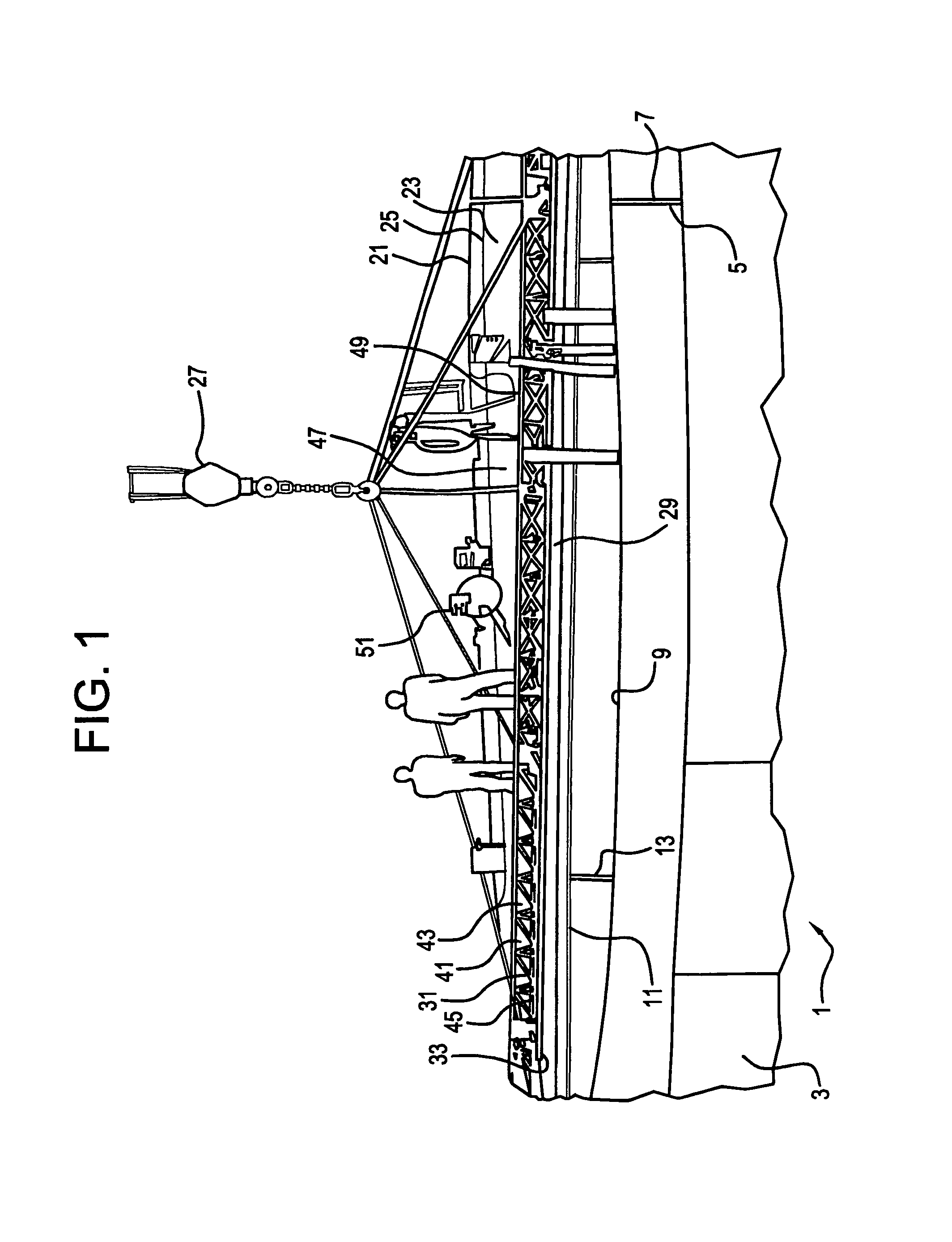
[0040]FIG. 1 shows a cylindrical ring shell and internal tables for supporting a flat plate of a roof while it is being assembled and constructed from welded parallel plates. The crane and lifting truss is shown placing a plate in position on the supporting table for subsequent welding to the longitudinal edge of the plates already assembled at the rear of the drawing.

[0041]As shown in FIG. 1, a cylindrical support structure with a circular upper edge is first constructed by welding curved plates in vertical welds at longitudinal ends of the curved plates.

[0042]The cylindrical ring shell is generally indicated by the numeral 1 and is formed from a series of vertical plates 3 which are curved around a vertical axis. Vertical welds 7 join longitudinal end edges 5 of the plates. A circular upper edge 9 of the cylindrical support shell supports the roof Tables 11 with legs 13 are mounted inside the cylindrical ring shell 1 to support the elongated roof plates 23 as they are assembled an...


PUM


Abstract

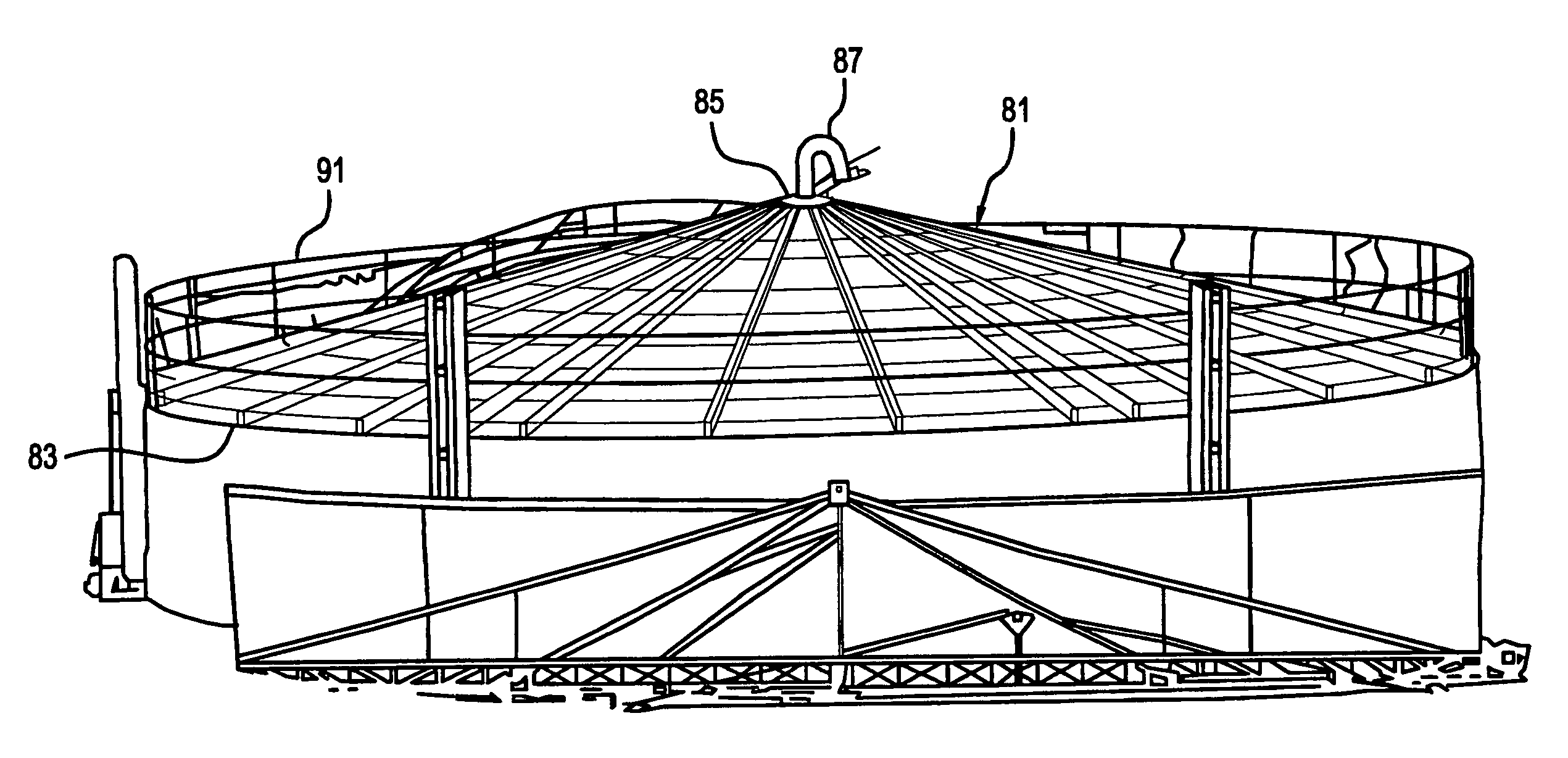
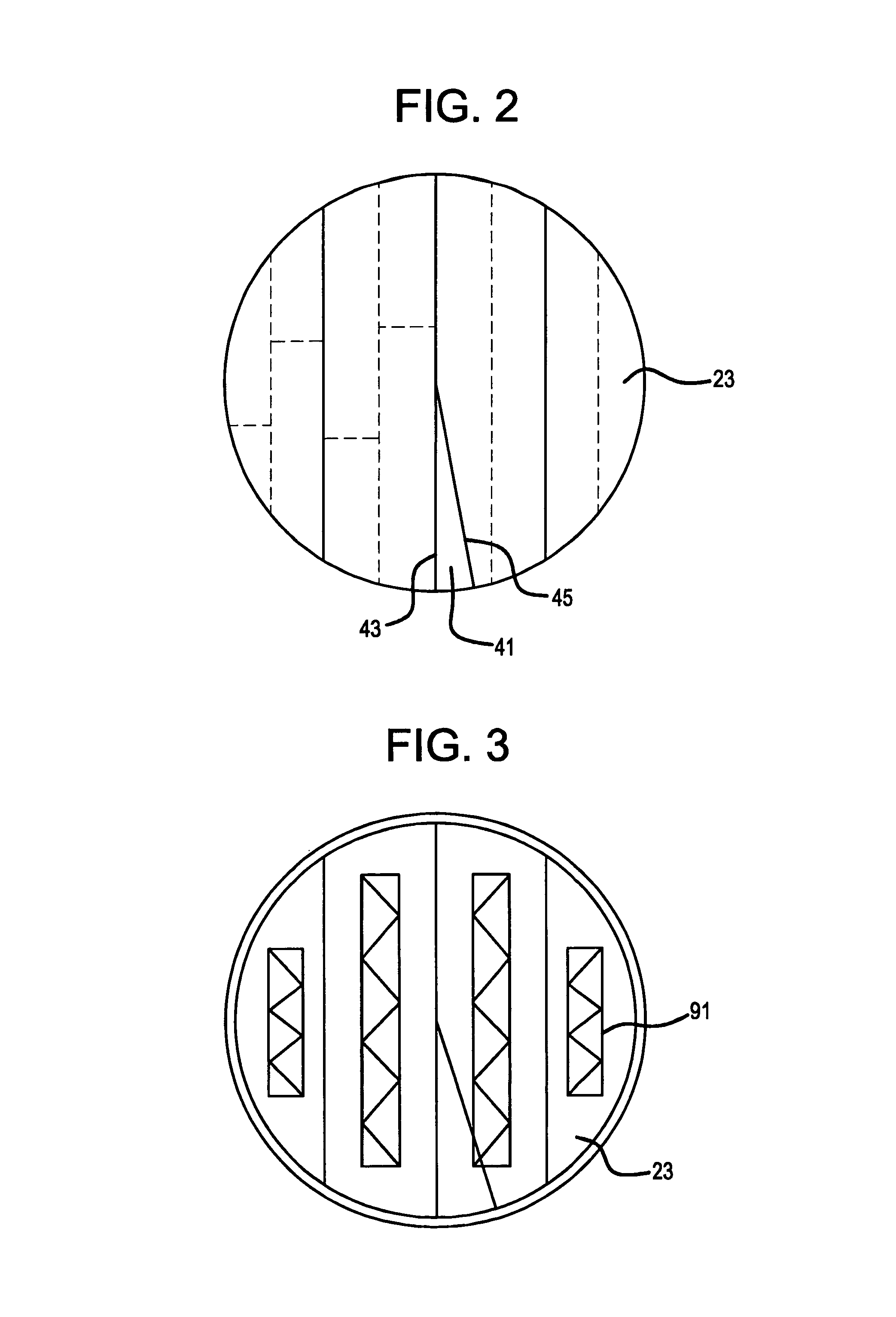
A new conical roof building method provides flat plates having straight abutting edges and curved outer edges. The plates are placed horizontally edge to edge except for a sectoral opening. The plates are welded together to form a flat disc-shaped blank, leaving an open sector of the blank. Radial supports are welded to a top of the disc-shaped blank. A center of the disc-shaped blank is lifted, forming a conical-shaped structure, closing and abutting edges of the open sector and touching edges of the formerly open sector are welded together, completing the forming of the conical roof.

Description

[0001]This application is a division of U.S. patent application Ser. No. 10 / 956,351 filed Oct. 4, 2004, now U.S. Pat. No. 7,743,582, which is hereby incorporated by reference in its entirety as if fully set forth herein.BACKGROUND OF THE INVENTION[0002]Placing roofs on large storage tanks and large circular structures is a difficult task which requires constructing and erecting support scaffolding to great heights above the ground and cutting, forming and building supports and plates at precise angles and constructing a precisely shaped supporting frame under the roof before welding of the roof elements together. The construction of domed and conical roofs requires a large amount of time, expense and skilled labor. In many cases support frames must be left enclosed within the roofs.[0003]Roofs are constructed atop buildings far from the ground. Tall scaffolding and extra precautions and safety procedures are required.[0004]Needs exist for better roof constructions.SUMMARY OF THE INV...

Claims


Application Information

Patent Timeline
Patent Type & Authority Patents(United States)
IPC IPC(8): E04B7/08E04B7/00
CPCE04B7/028
Inventor PETRICIO YAKSIC, DAVOR
Owner PETRICIO YAKSIC DAVOR
Learn More