Tire valve tool having air communication means

a technology of air communication and tire valve, which is applied in the field of tire valve tools, can solve the problems of device not offering the means of pressing down the valve core for inflation, and the device fails to provide a means of filling the tire through the tool,

Inactive Publication Date: 2014-05-20
RENAKER ROBERT +1
View PDF12 Cites 6 Cited by
  • Summary
  • Abstract
  • Description
  • Claims
  • Application Information

AI Technical Summary

Benefits of technology

[0015]In view of the foregoing disadvantages inherent in the known types of tire valve tools now present in the prior art, the present invention provides a new tire valve tool that can be utilized for providing convenience for the user when replacing a Schrader valve core or replacing the tube of a pneumatic tire.
[0018]Another object of the present invention is to provide a tire valve tool that can remove and replace the valve core of a Schrader valve from the valve stem, clean the internal and external threading of the valve stem, support the valve stem when loosely placed through the rim, and finally filling the attached tire with air without removing the tool from the valve stem.
[0019]Yet another object of the present invention is to provide a tire valve tool that is X-shaped to facilitate hand tightening and loosening a tire valve core, and also facilitate cleaning of the tire valve stem threading using the hand wound thread taps of the tool.
[0020]Another object of the present invention is to provide a tire valve tool that includes an internal conduit and a spring biased check valve that allows air to be communicated through the tool when connected to the valve stem, whereby the user can maintain the position of the valve stem through the rim and fill the tire with air without removing the tool.
[0021]A final object of the present invention is to provide a tire valve tool that may be readily fabricated from materials that permit relative economy and are commensurate with durability.

Problems solved by technology

However, similar to the Cooley device, the Gielow device fails to provide a means of filling the tire through the tool when in use as provided herein.
The Colley device offers no means of pressing down the valve core for inflation and relies on air pressure to depress the same while inflating a tire.

Method used


Image

  • Tire valve tool having air communication means
  • Tire valve tool having air communication means
  • Tire valve tool having air communication means

Examples


Embodiment Construction

[0029]Reference is made herein to the attached drawings. Like reference numerals are used throughout the drawings to depict like or similar elements of the tire valve tool. For the purposes of presenting a brief and clear description of the present invention, the preferred embodiment will be discussed as used for removing and replacing a valve core from within a Schrader valve stem, cleaning the threading thereof, and allowing the user to communicate air through the valve without first removing the tool. The figures are intended for representative purposes only and should not be considered to be limiting in any respect.

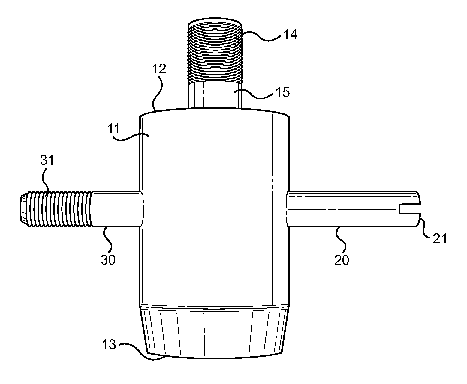
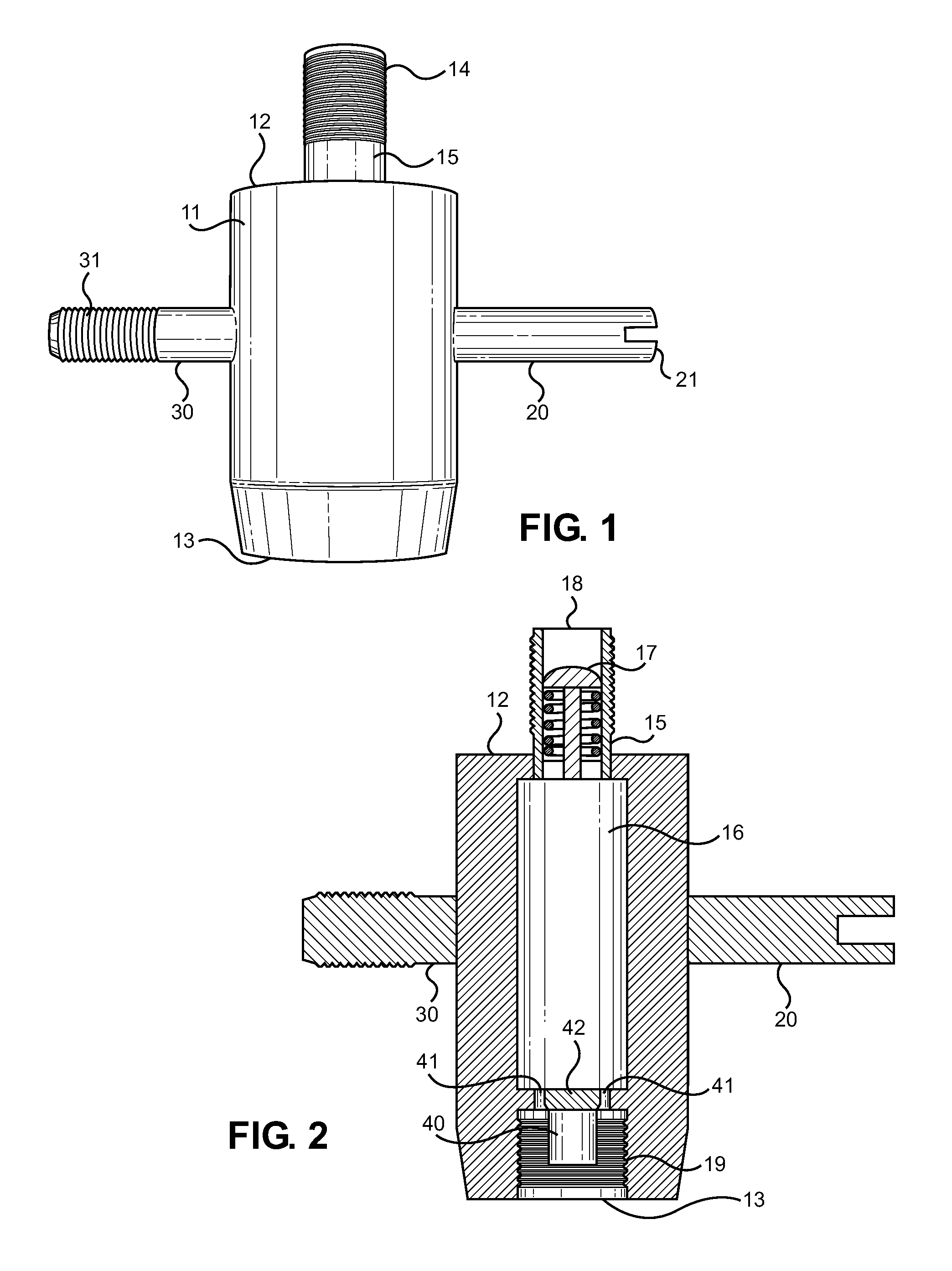
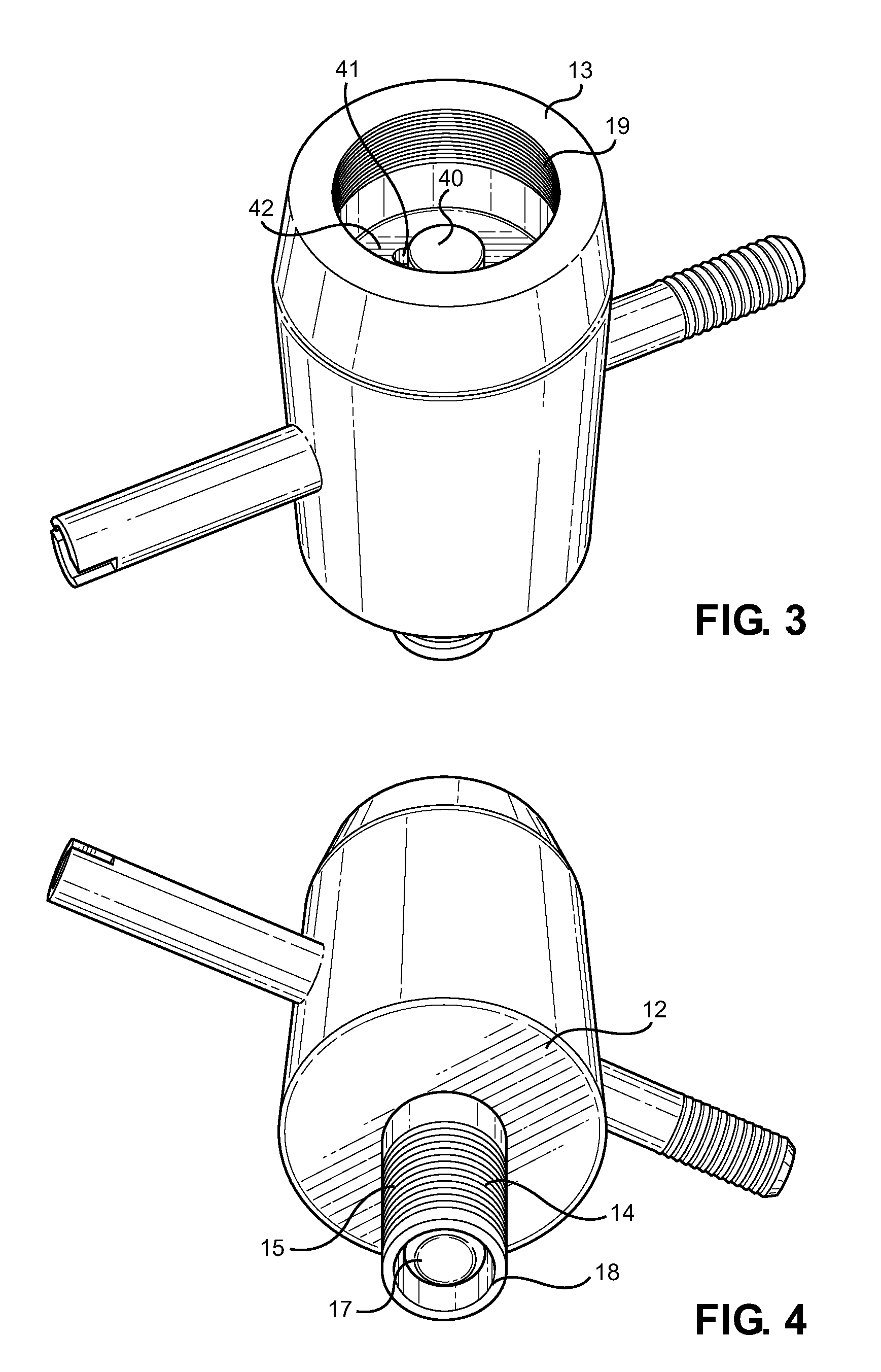
[0030]Referring now to FIG. 1, there is shown a frontal view of the tire valve tool of the present invention. The device comprises a tool body 11 having a first 12 and second 13 end, cylindrical sidewalls and an open interior conduit. Disposed on opposing sides of the body 11 are a valve core removal arm 20 and a valve stem tap arm 30. Both arms extend from the body 1...


PUM

PropertyMeasurementUnit
internal pressureaaaaaaaaaa
stabilityaaaaaaaaaa
pressureaaaaaaaaaa

Abstract

A multipurpose tire valve tool is provided for the purposes of maintenance of a Schrader valve and for replacing the tube of a pneumatic tire. The tool comprises a valve core removal key, a valve stem tap arm, a first air inlet end, and a second valve stem attachment end. Through the body of the tool is an air conduit and an internal valve core post for depressing the same. A check valve along the air inlet end allows air to be communicated into the tool, whereby the air flows therethrough and into an attached Schrader valve for filling the tire tube while the tool is thereattached. The tool facilitates removal of the valve core, cleaning of the valve stem threads, and filling the tire or tire tube with air while the tool maintains the position of the valve stem through the rim.

Description

CROSS REFERENCE TO RELATED APPLICATION[0001]This application claims the benefit of U.S. Provisional Application No. 61 / 671,897 filed on Jul. 16, 2012, entitled “4 Way Air Tool.” The above identified patent application is herein incorporated by reference in its entirety to provide continuity of disclosure.BACKGROUND OF THE INVENTION[0002]1. Field of the Invention[0003]The present invention relates to a tire valve tool for replacing the valve core of a tire Schrader valve and filling a flat tire with air. More specifically, the present invention pertains to a new and improved, multi-function valve core tool that is capable of replacing a Schrader valve core in a pneumatic tire valve stem and thereafter filling the tire with air without requiring the user to remove the tool after the core has been installed.[0004]Bicycle, motorcycle, and automobile tires are pneumatic vessels that are in contact with the ground during vehicle operation and influence the grip of the vehicle to the groun...

Claims


Application Information

Patent Timeline
Patent Type & Authority Patents(United States)
IPC IPC(8): B25B1/00
CPCB60C25/18Y10T29/53596Y10T137/3724Y10T29/53909Y10T29/53591
Inventor RENAKER, ROBERTRENAKER, REVA
Owner RENAKER ROBERT
Why Eureka
Try Eureka