
Modular electrical harness for military vehicles adapted with the multiple integrated laser engagement system

a technology of laser engagement and module harness, which is applied in the direction of wheel arrangement, electric devices, transportation and packaging, etc., can solve the problems of unable to modify the harness to facilitate additional systems, the entire harness has to be removed, and still kills commanders, etc., to achieve faster and easier troubleshooting and replacement of certain sections of the harness, and achieve faster and easier product replacement. , the effect of facilitating the replacemen

Inactive Publication Date: 2009-07-14
FONDRIEST WILLIAM
View PDF9 Cites 2 Cited by
  • Summary
  • Abstract
  • Description
  • Claims
  • Application Information

AI Technical Summary

Benefits of technology

The modular design facilitates quicker vehicle turnaround in training exercises by allowing specific harness sections to be replaced without disrupting the entire system, reducing spare parts inventory, and enabling the integration of new capabilities without replacing the entire harness.

Problems solved by technology

As a result a MILES emulating an M-16 rifle cannot kill a tank or armoured personnel carrier (APC), but could still kill a commander visible in the hatch of the vehicle.
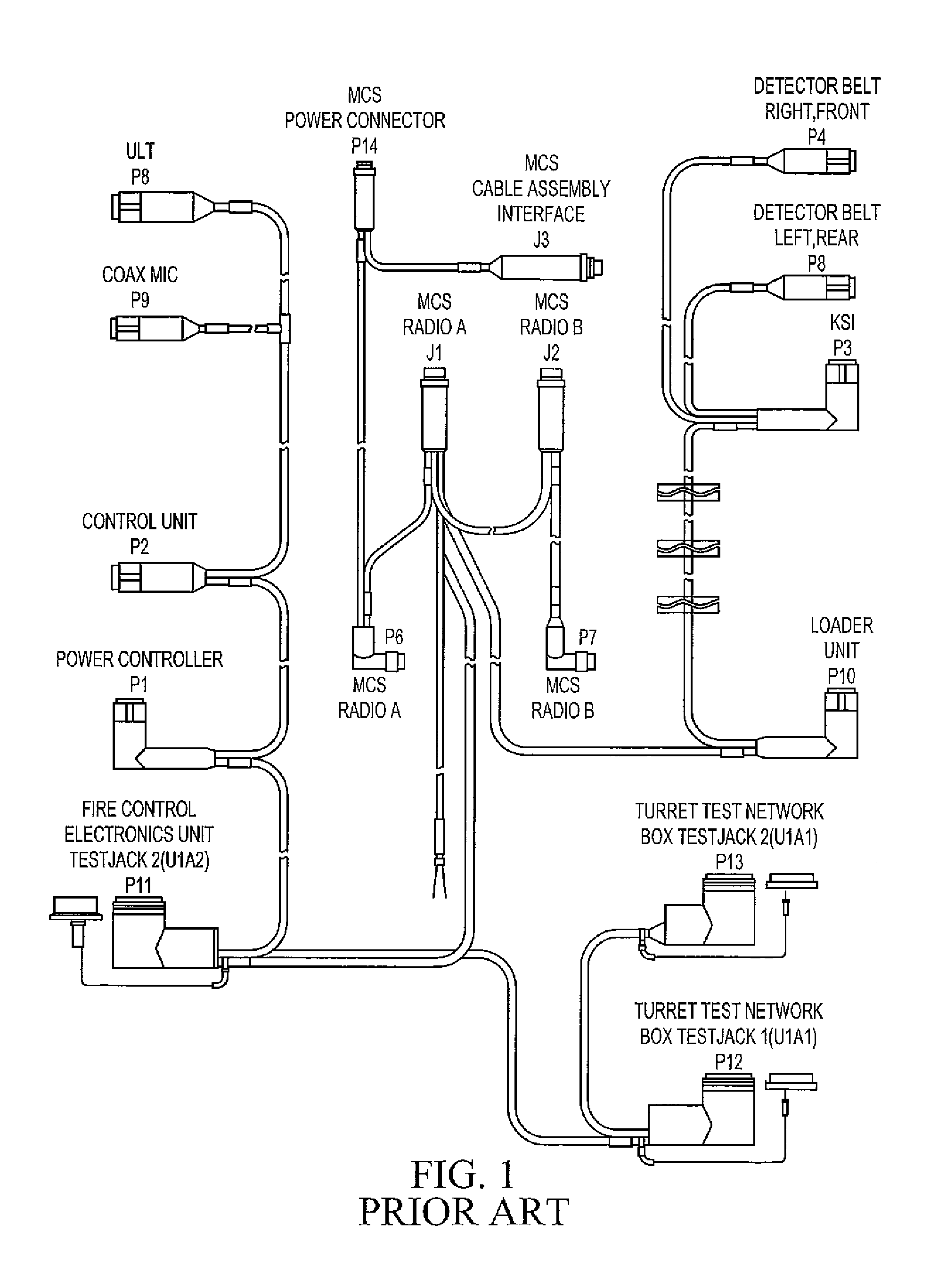
One of the major setbacks of the current MILES 2000 system that is used on various military vehicles is the cable system that is used to connect the various MILES gear components with one another along with applicable systems in the vehicle.
The cables currently in use on the MILES system are manufactured using a process known as “mold in place” and / or “over mold.” This harness design does not lend itself to repairs and makes modification of the harness to facilitate additional systems virtually impossible.
The current harness is also not modular, which means that when a particular section of the harness is damaged, the entire harness has to be removed from the vehicle and a new one installed.
Since military vehicles are used in harsh environments, even during training, damage to the MILES harnesses is quite common.
This damage causes the training exercises to be halted and / or delayed while new harnesses are installed.
Also, as new equipment becomes available to enhance the realism of training, integration of this equipment into the existing MILES system is problematic, because the exiting cables do not allow for modification to accept additional capabilities.

Method used


Image

  • Modular electrical harness for military vehicles adapted with the multiple integrated laser engagement system
  • Modular electrical harness for military vehicles adapted with the multiple integrated laser engagement system
  • Modular electrical harness for military vehicles adapted with the multiple integrated laser engagement system

Examples


Embodiment Construction

[0022]Both combat vehicles, such as the M1A1 Abrams main battle tank, and various support vehicles can be instrumented using vehicle-specific MILES kits. Vehicle kits typically include a number of hardware components that must be electrically connected by cables. As noted above, the prior art provides a single cable system having multiple branches terminating in connectors for use in connecting the various vehicle hardware components together. These prior art cables are unitary single piece cables manufactured using a process known as “mold in place” and / or “over mold.”FIG. 1 depicts a cable system typical of the prior art for adapting the M1A1 / M1A2 main battle tank with the MILES 2000 system.

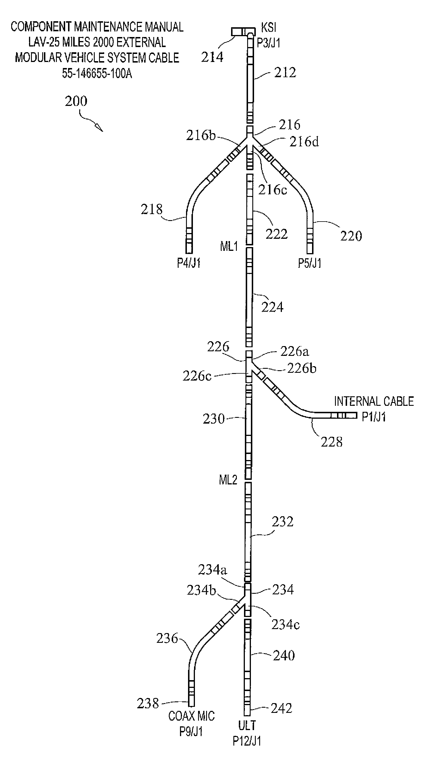
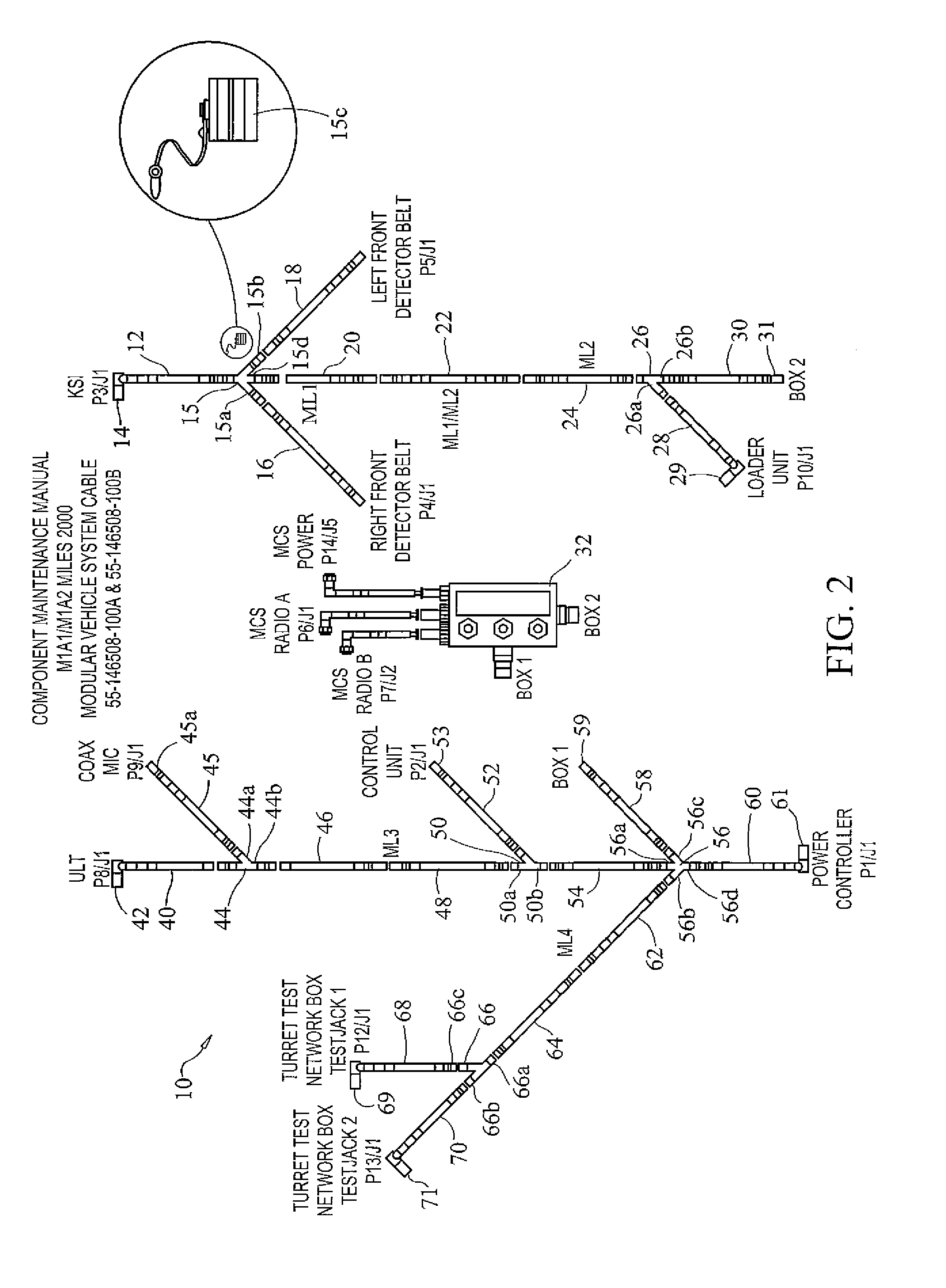
[0023]Turning now to the drawings, FIGS. 2-6 depict various embodiments of modular vehicle system cables in accordance with the present invention.

I. M1A1 / M1A2 Main Battle Tank

[0024]FIG. 2 depicts a modular vehicle cable system, generally referenced as 10, adapted for use with the M1A1 and M1A2 ...


PUM


Abstract

A modular vehicle cable system for adapting military vehicles with the MILES 2000 Multiple Integrated Laser Engagement System used by the United States Armed Forces and other armed forces around the world for training purposes is disclosed. A modular vehicle cable system is provided to allow the user the ability to troubleshoot, remove, and replace certain sections of the system quicker and easier than previously allowed. The design also allows for the installation of additional systems with only minor modifications. The modular vehicle cable system not only makes a cable system more reliable through inherent design, but also allows the user the ability to remove and replace a specific portion of a cable system without disrupting the other systems associated with a cable system. The modular nature of the cable system reduces maintenance and repair times by enabling rapid diagnosis and replacement of defective cable components and sections thereby maximizing training exercises by minimizing vehicle down time.

Description

CROSS REFERENCE TO RELATED APPLICATIONS[0001]This application is a continuation-in-part of U.S. patent application Ser. No. 10 / 693,801, filed on Oct. 24, 2003, now U.S. Pat. No. 7,135,790.STATEMENT REGARDING FEDERALLY SPONSORED RESEARCH OR DEVELOPMENT[0002]The U.S. Government has a paid-up license in this invention and the right in limited circumstances to require the patent owner to license others on reasonable terms as provided for by the terms of Contract No. M67854-05-C-8009, dated Mar. 23, 2005, awarded by the United States Marine Corps.COPYRIGHT NOTICE[0003]A portion of the disclosure of this patent document contains material that is subject to copyright protection. The copyright owner has no objection to the facsimile reproduction by anyone of the patent document or patent disclosure as it appears in the Patent and Trademark Office patent file or records, but otherwise reserves all copyrights rights whatsoever.BACKGROUND OF THE INVENTION[0004]1. Field of the Invention[0005]Th...

Claims


Application Information

Patent Timeline
Patent Type & Authority Patents(United States)
IPC IPC(8): B60L1/00B60L3/00
CPCH02G3/00B64C25/36B60L1/00B60L3/00
Inventor FONDRIEST, WILLIAM
Owner FONDRIEST WILLIAM
Learn More