Pneumatic rotary actuator

a rotary actuator and pneumatic control technology, applied in the direction of fluid-pressure actuators, positive displacement engines, reciprocating piston engines, etc., can solve the problems of high mechanical properties and hardness, high cost, high mechanical properties, etc., and achieve the effect of low cost, minimum tolerances, and high mechanical performan

Inactive Publication Date: 2007-09-06
GIMATIC SRL
View PDF4 Cites 7 Cited by
  • Summary
  • Abstract
  • Description
  • Claims
  • Application Information

AI Technical Summary

Benefits of technology

[0006]Starting from the above premises, one objective of the invention is to create the conditions so that a pneumatic rotary actuator of the type mentioned above can be made in a simpler and more economic way, at least by minimising times and costs of making and assembling some of its components, but nonetheless ensuring a high quality and reliable product.
[0007]Another objective of the invention is to propose a pinion which can be produced using simplified moulding techniques, without however having to turn to mechanical machining on machine tools or at least significantly limiting their use.
[0009]Therefore and advantageously, on the one hand the base flange and the pinion head can be made using moulding techniques, such as compression moulding, die-casting, sinterisation and the like, using initial low-cost materials such as zama (Zn+AL+Mg alloy) whereas the pins can be made out of a material with very high mechanical performance such as steel.
[0010]The abovementioned moulding techniques can be used to produce finished articles even with relatively complicated shapes, with minimum tolerances, with a high degree of precision, and with the possibility of using surface treatment, where required, so that the base flange and pinion head do not require further intervention and mechanical machining. In other words, the base flange and cover or head can be relatively easily produced at a limited cost, but they cannot be integrated with traditional cog connections made of the same material, in that they would not, in this case, have sufficiently reliable strength for use under force. Whereas, although made of a low-cost material with low mechanical properties, they are part of the assembly of the pins which, being made of a material with high mechanical properties, guarantee the required mechanical strength and wear resistance in coupling with a complementary means, such as the rack of the control piston in the range of a rotary actuator.

Problems solved by technology

Evidently, this machining procedure of the pinion necessitates considerable time and is costly, which are further increased if you consider that in order to ensure the required resistance under force and the wear on its cogs, the pinion must be made out of a material with very high mechanical properties and hardness, therefore in itself relatively precious and costly.
However, on the one hand, also in this case the flanges were made by machining items made of a high strength material such as steel, the same being valid for the pins but, on the other hand, such a pinion structure has never been used in rotary actuators.

Method used


Image

  • Pneumatic rotary actuator
  • Pneumatic rotary actuator
  • Pneumatic rotary actuator

Examples


Embodiment Construction

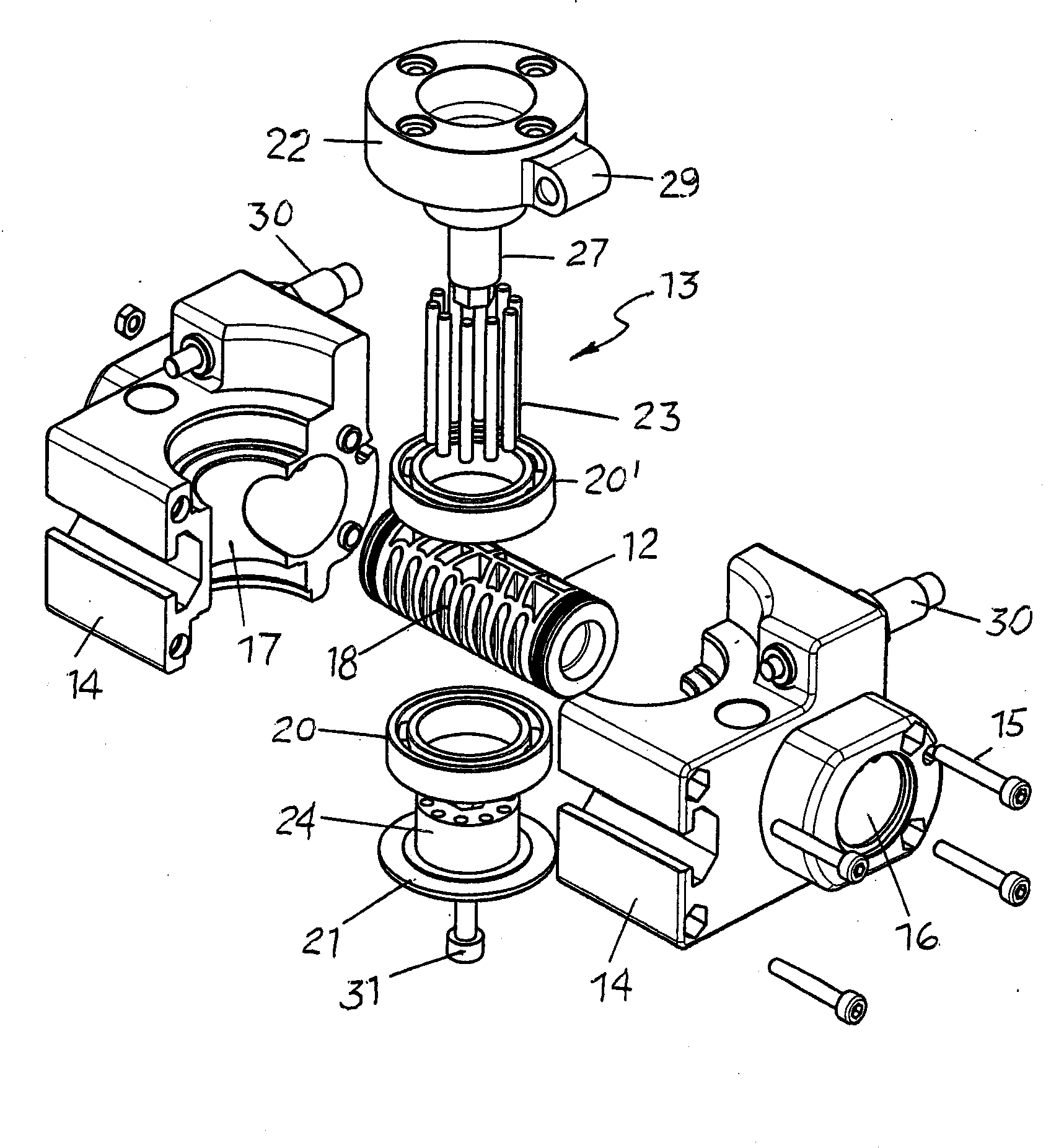
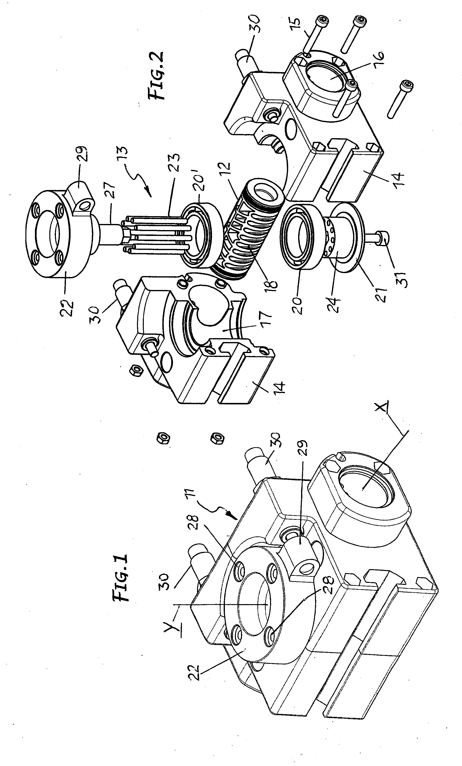
[0015]As shown, the rotary actuator under examination basically comprises a body 11, a control piston 12 and a pinion 13.

[0016]The body 11 can be made out of a single piece or, better, as shown in FIG. 2, out of two complementary opposed elements 14, coupled and fixed together by screws 14, 15. In any case, the body 11, whether single or made up of two elements, forms a chamber 16 which extends according to an X axis and a housing 17 with a Y axis at a right angle to the X axis of the chamber, the latter being basically tangent and crossing the housing 17.

[0017]The piston 12 has, on one side, a rack 18, it is housed in a chamber 16 and moves by reciprocating motion, driven by a fluid, usually compressed air, delivered to said chamber alternatively from opposite sides of the piston.

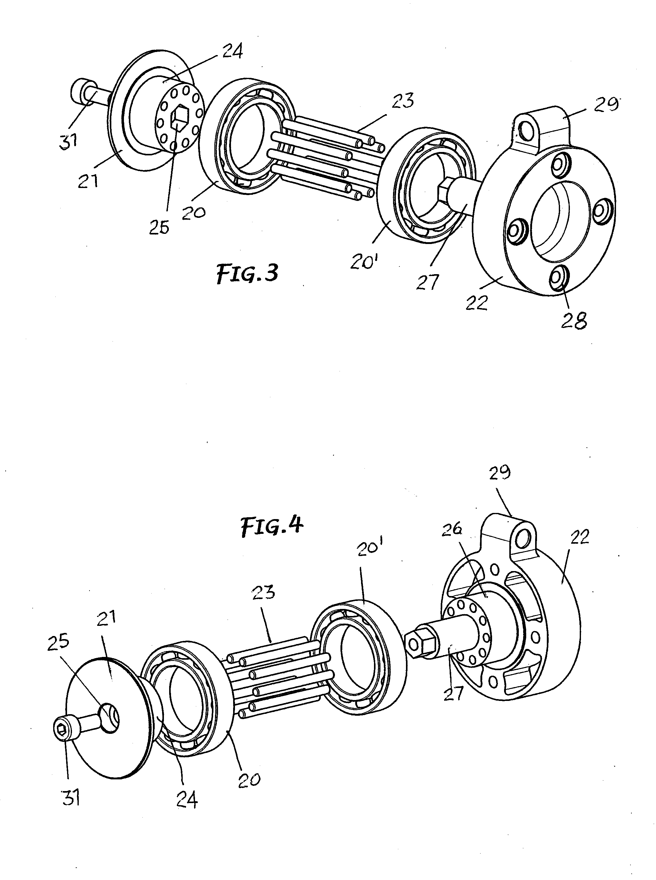
[0018]The pinion 13 is housed and rotates in said housing 17 with the interposition of support bearings 20, 20′ and it engages with the rack of the piston 12.

[0019]The pinion 13 comprises a base flange 21,...


PUM


Abstract

The invention concerns a pneumatic control rotary actuator that incorporates a control piston of a rack toothing engaging with a pinion to cause it to rotate together with an item holder device; the pinion has toothing made up of several parallel pins (23) spaced at an angle, positioned and held orderly between a base flange (21) and an item holder disk head (22); the base flange and the disk are each produced by compression moulding, die-casting, sinterisation and the like, using a low mechanical resistance material whereas said pins are made of some other material with high mechanical properties and hardness.

Description

FIELD OF THE INVENTION[0001]This invention concerns a pneumatically controlled rotary actuator for moving and orienting parts or components in mechanical operations, assembling and the like.State of the Technique[0002]The type of pneumatically controlled rotary actuator taken into consideration comprises substantially a body forming a chamber and a housing with planes at right angles, with the chamber practically tangent to the housing, where a pneumatic piston subject to alternating movements is housed, and in said housing is also housed and supported a rotating cogged pinion with an item holder device, and where the piston has a rack cogged attachment designed to engage with the pinion to turn the latter together with the item holder device in response to the alternating movements of the piston.[0003]According to the known technique, the cogged pinion for such an actuator is made out of a single piece through mechanical machining and precision cogs on machine tools.[0004]Evidently...

Claims


Application Information

Patent Timeline
Patent Type & Authority Applications(United States)
IPC IPC(8): F16H21/00
CPCF15B15/065Y10T74/18056Y10T74/1967
Inventor MAFFEIS, GIUSEPPE
Owner GIMATIC SRL
Why Eureka
Try Eureka