Light source and method for producing a light source

a technology of light source and light source, which is applied in the direction of discharge tube/lamp details, discharge tube luminescnet screen, gas-filled discharge tube, etc., can solve the problems of large portion of consumed electric power being uneconomical, inefficient in converting electric power to visible light output, etc., and achieve reliable filament production and influence of conductivity.

Inactive Publication Date: 2005-06-07
IP2H AG
View PDF19 Cites 8 Cited by
  • Summary
  • Abstract
  • Description
  • Claims
  • Application Information

AI Technical Summary

Benefits of technology

[0034]By rolling the filament to a foil after its preparation, it is possible to carry out an additional compacting step in the method, whereby conductivity is likewise influenced.
[0035]As regards a particularly reliable production of the filament, it would be possible to insert the filament after making it available, into a bulb that is open at two ends, and to bond it electrically at one end of the bulb. Thus, after having been provided and rolled, if necessary, the filament would be already available in the bulb in a protected manner. This provides a mechanical protection during further steps of the method.

Problems solved by technology

All so far known, electrically operated types of light sources have the disadvantage that they are very inefficient with respect to converting electric power to visible light output.
The largest portion of the consumed electric power is an uneconomical dissipation primarily in the form of heat.
As a result, the filament or glow wire undergoes a kind of backheating.
The known filaments present a problem in that, for example, the known spiral form of the filaments or glow wires permits only a very slight absorption of the reflected heat radiation, since the largest portion of the heat radiation is reflected past the thin spiral wire.
Thus, an effective absorption or backheating is not possible in the case of conventional filaments or glow wires.
Consequently, a high conversion efficiency is not realizable with conventional light sources.

Method used


Image

  • Light source and method for producing a light source
  • Light source and method for producing a light source
  • Light source and method for producing a light source

Examples


Embodiment Construction

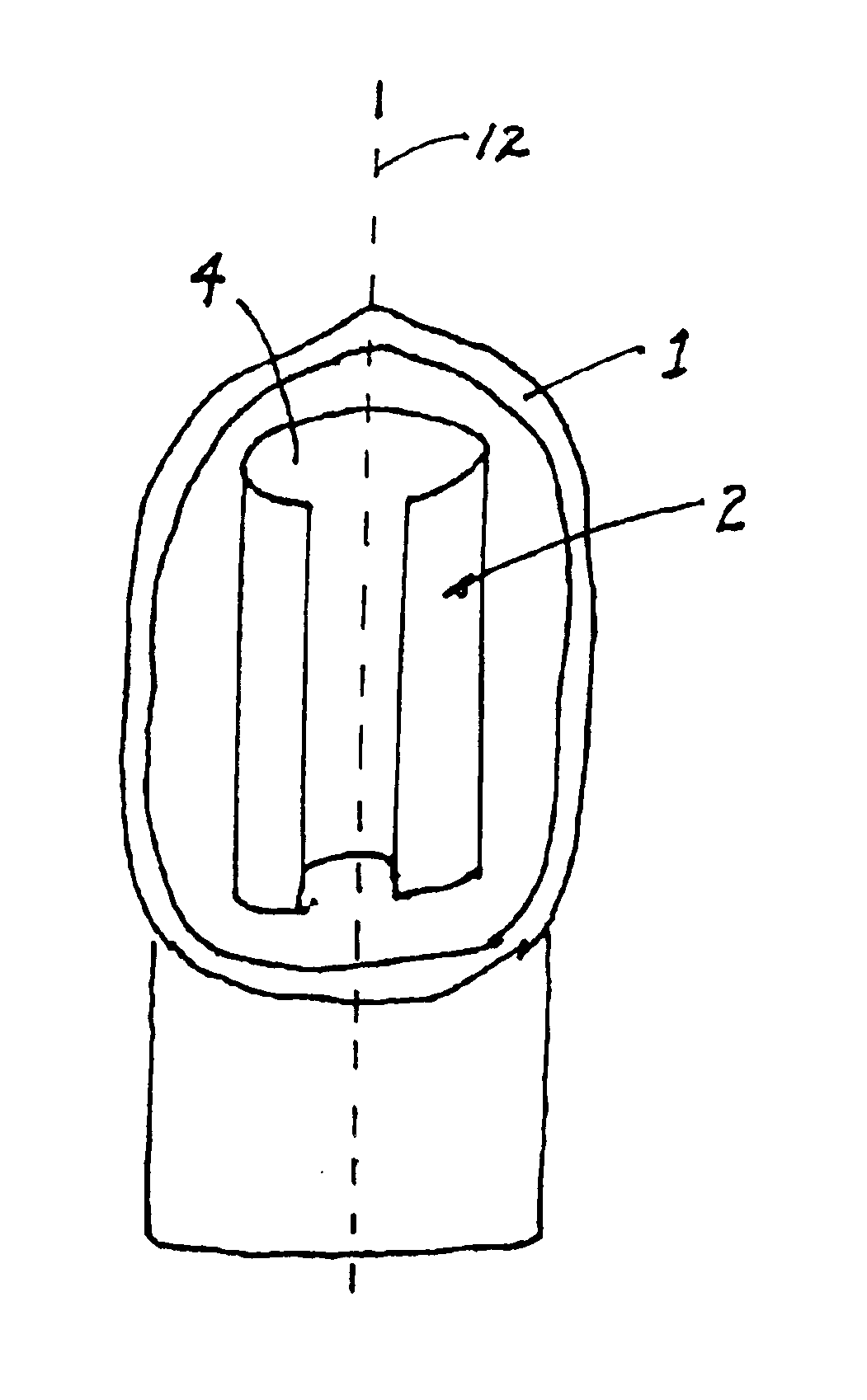
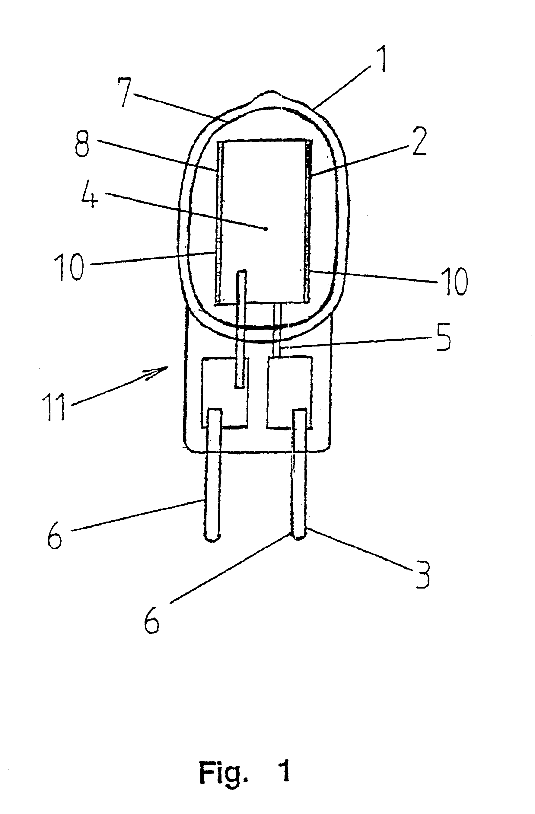
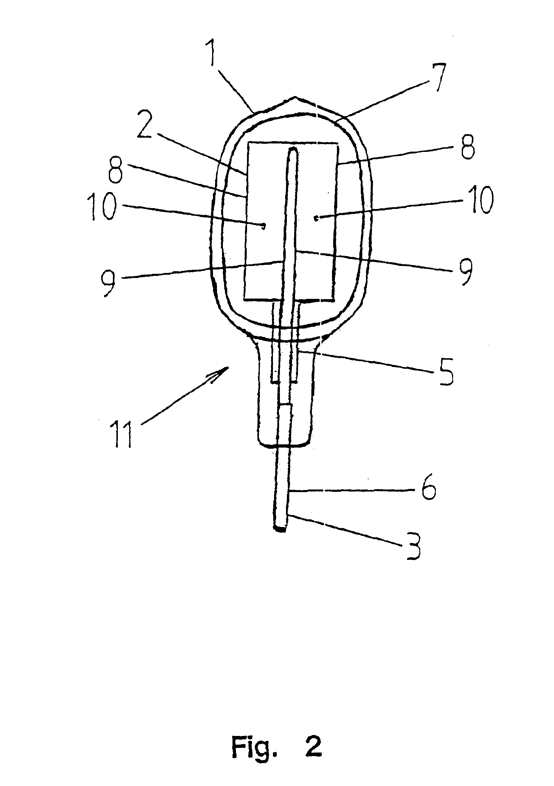
[0047]FIG. 1 is a perspective side view of an embodiment of a light source according to the invention. The light source is designed and constructed as an incandescent lamp, which comprises a bulb 1 that accommodates a filament 2 or incandescent element. For heating the filament 2, a heating device 3 is provided, which makes available an electric current. The heated filament 2 emits both visible light and heat radiation.

[0048]With respect to a high conversion efficiency of the light source, the filament 2 comprises a flat section 4. The flat section 4 enables a high degree of absorption of the heat radiation reflected from the inner side of bulb 1 and originally radiated from filament 2, whereby the filament 2 is quasi backheated. Therefore, for achieving the same light output of the light source, it is possible to supply to the light source less energy than is the case with conventional light sources. Consequently, it is possible to operate the light of the present invention with le...


PUM


Abstract

A light source, in particular incandescent lamp, with a bulb (1), a filament (2) arranged in the bulb (1), and a heating device (3) for the filament (2), the filament (2) emitting both visible light and heat radiation, is designed and constructed with respect to a high conversion efficiency between an electrical power input and emitted light output such that the filament (2) includes a flat section (4). A light source of this type may be produced by a method, wherein initially a filament (2) of a sintered metal powder is provided. Subsequently, the filament (2) is exposed to an atmosphere of carbon dioxide or of carbon dioxide and inert gas for forming a metal carbide. Finally, the filament (2) is sealed into the bulb (1).

Description

[0001]“This application is a 371 of PCT / DE00 / 00912, filed on Mar. 24, 2000.”BACKGROUND OF THE INVENTION[0002]The invention relates to a light source, in particular incandescent lamp, with a bulb, a filament arranged in the bulb, and a hearing device for the filament, the filament emitting both visible light and heat radiation. Furthermore, the invention relates to a method for producing a light source of the above mentioned type.[0003]Light sources of the described type have been known from practice for a long time, and they exist in a large variety of designs and sizes. In this connection, for example, incandescent lamps are known as electrical light sources, in which it is common to bring a tungsten filament by electrical Joule heat to a highest possible temperature. In this process, a temperature radiation is generated. The light yield of incandescent filaments considerably increases as the temperature rises. Besides that, also so-called nonthermal sources of radiation are known,...

Claims


Application Information

Patent Timeline
Patent Type & Authority Patents(United States)
IPC IPC(8): H01K3/00H01K1/00H01K1/02H01K1/14H01K3/02H01K1/04H01K1/08H01K1/10H01K1/32H01K11/00
CPCH01K1/02H01K3/02H01K1/14
Inventor ARNOLD, JORG
Owner IP2H AG
Why Eureka
Try Eureka