Slip conveyor

a conveyor and sleeve technology, applied in the direction of conveyor parts, conveyors, jigging conveyors, etc., can solve the problem of not being able to adapt to the varying demands of weighing and packaging machines

Active Publication Date: 2014-05-20
TNA AUSTRALIA
View PDF10 Cites 4 Cited by
  • Summary
  • Abstract
  • Description
  • Claims
  • Application Information

AI Technical Summary

Benefits of technology

[0010]the first conveyor tray includes an end portion located adjacent the second conveyor tray with the end portion being movable relative to the second tray to provide a longitudinally extending gap between the first and second trays via which product is delivered from the assembly, the gap having an area of a desired size and having a longitudinal length and a transverse width, with said width being adjustable by movement of said end portion relative to the second tray to thereby alter the size of said area.

Problems solved by technology

A disadvantage of these known slip conveyors is that they cannot adapt to the varying demands of the different weighing and packaging machines.

Method used


Image

  • Slip conveyor
  • Slip conveyor
  • Slip conveyor

Examples


Embodiment Construction

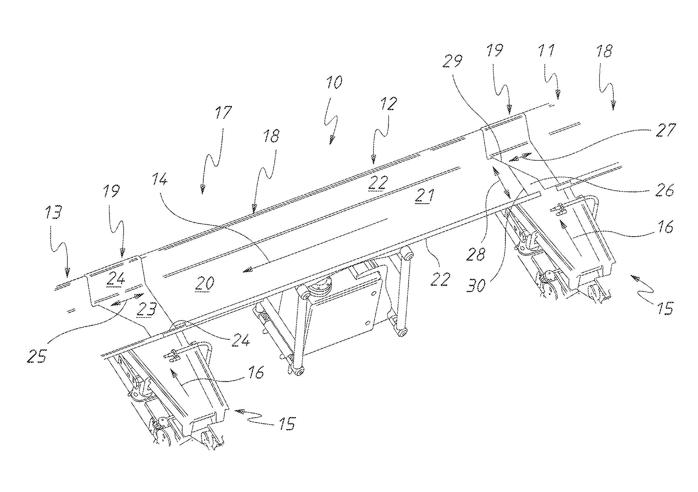
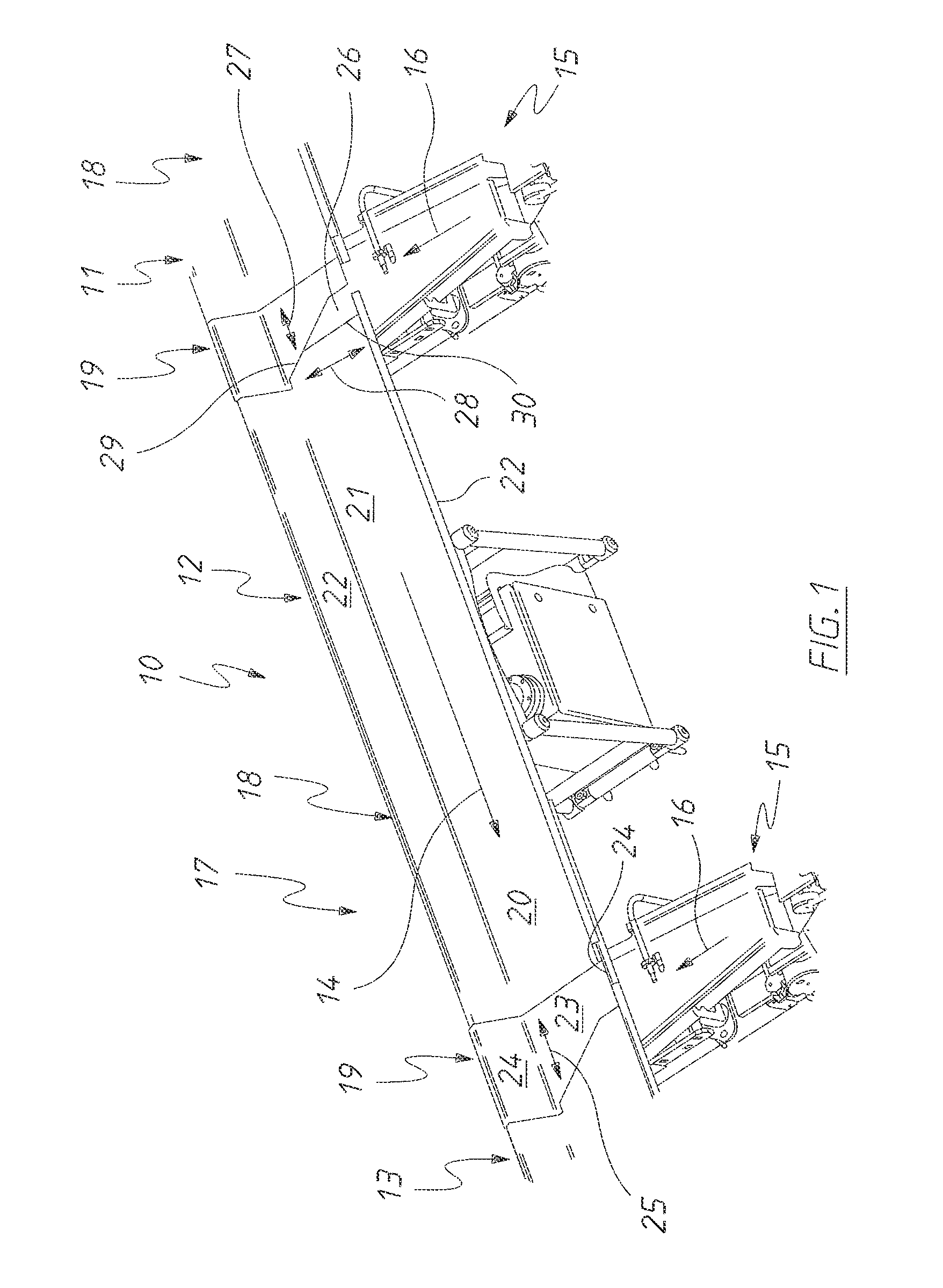
[0032]In the accompanying drawings there is schematically depicted a slip conveyor assembly 10. The assembly 10 includes a plurality of conveyor trays 11, 12 and 13 that are operated to convey material in the direction 14. Located below the trays 11, 12 and 13 are transverse conveyors 15. Material being conveyed by the trays 11, 12 and 13 can be selectively delivered to the transverse conveyors 15 for delivery to packaging machines. The conveyors 15 transport conveyed material in the direction 16. The conveyors 15 may also be slip conveyors.

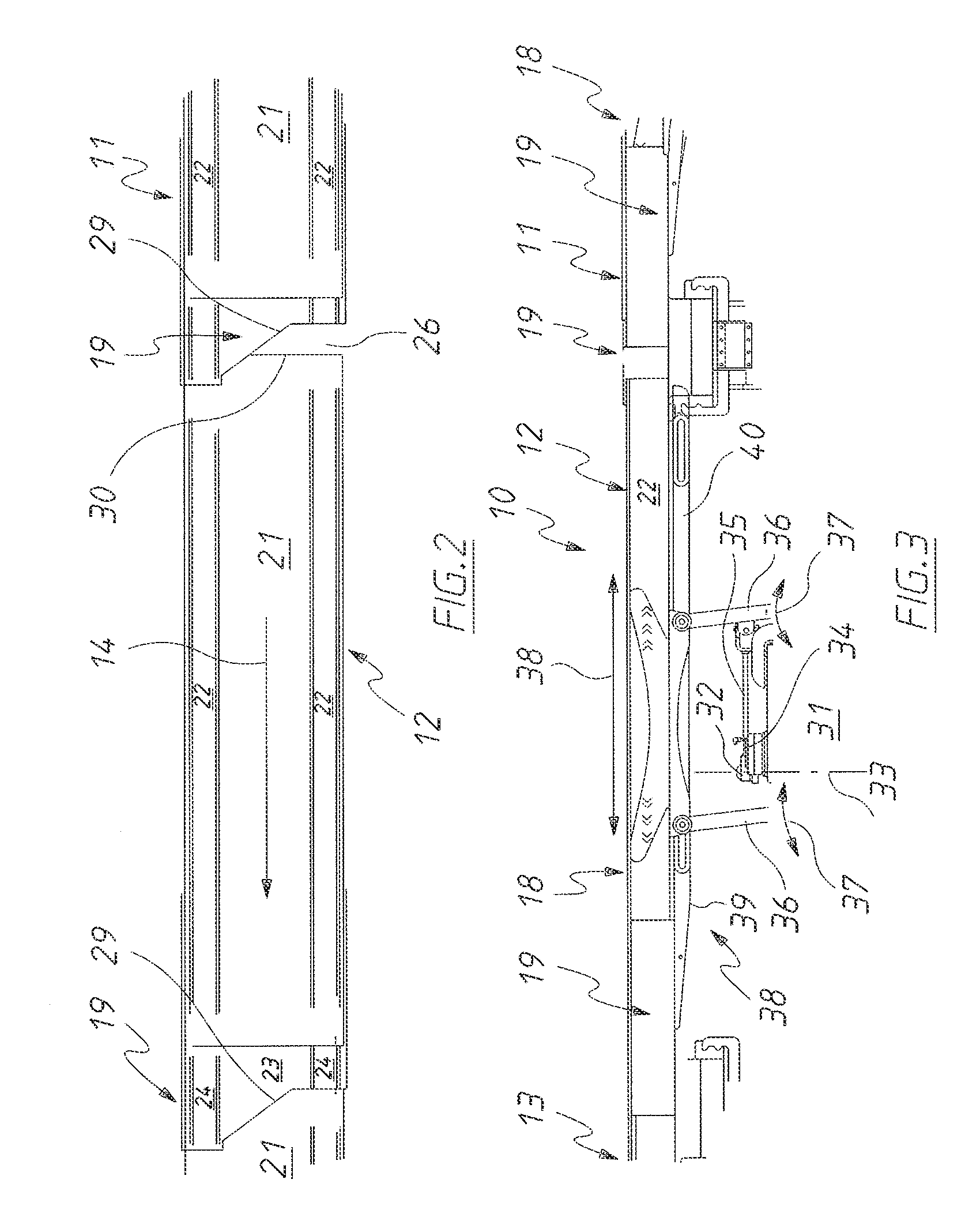
[0033]Each of the conveyors 11, 12 and 13 includes a longitudinally extending tray 17 that includes a base 18 and an end portion 19. The base 18 and end portion 19 provide a longitudinally extending surface 20 upon which the material rests to be conveyed in the direction 14.

[0034]The base 18 includes a longitudinally extending bottom wall 21 and a pair of upwardly extending side walls 22. The side walls 22 are attached to the bottom wall 21 and d...


PUM


Abstract

A slip conveyor (10) having a plurality of trays (11, 12, 13). Each of the trays (11, 12, 13) has an end portion (19) with an edge (29) inclined to the longitudinal direction of movement (14) of the tray (11, 12, 13).

Description

[0001]This application claims priority to Australian Application No. 2011901414, filed Apr. 14, 2011, the disclosure of which is incorporated by reference herein.TECHNICAL FIELD[0002]The present invention relates to slip conveyors and more particularly but not exclusively to slip conveyors employed in the packaging industry.BACKGROUND OF THE INVENTION[0003]Slip conveyors include longitudinally extending trays that are longitudinally vibrated (reciprocated) to transfer material along the conveyor. The longitudinal oscillation is rapid in one direction and slow in the other. The material is transported in the slow direction. Conveyors, including slip conveyors are described in U.S. Pat. No. 7,228,957 and U.S. patent application Ser. No. 11 / 108,052 (lodged on 14 Apr. 2005) and Ser. No. 11 / 263,762 (lodged on 31 Oct. 2205).[0004]In the packaging industry, particularly the industry relating to the packaging of snack foods, product is delivered to a group of weighing machines, each of the ...

Claims


Application Information

Patent Timeline
Patent Type & Authority Patents(United States)
IPC IPC(8): B65G27/06
CPCB65G27/12B65G27/04B65G27/34B65G47/78B65G27/32
Inventor TAYLOR, ALFRED, ALEXANDER
Owner TNA AUSTRALIA
Why Eureka
Try Eureka