AI technical title is built by Patsnap AI team. It summarizes the technical point description of the patent document.
a technology of multiple beams and antennas, applied in antennas, antenna details, electrical equipment, etc., can solve the problems of increasing fuel consumption of commercial and military vehicles and aircraft, reducing mission range, and large height, and achieve the effect of low cost and low cos
Active Publication Date: 2014-05-20
MITRE SPORTS INT LTD
View PDF3 Cites 2 Cited by
Summary
Abstract
Description
Claims
Application Information
AI Technical Summary
This helps you quickly interpret patents by identifying the three key elements:
Problems solved by technology
Method used
Benefits of technology
Benefits of technology
[0007]Another advantage of the invention is that the antenna can include a beamforming lens, feed elements, and a radiating aperture all in one.
[0008]Another advantage of the invention is that the antenna can track multiple objects or wireless communication nodes while the platform the antenna is deployed upon is moving. Other advantages include the antenna can be deployed on the bottom of an aircraft to look down for air-to-ground communications or for some radar applications and low cost.
[0009]Other advantages of the invention include a very low cost in comparison to a phased array antenna.
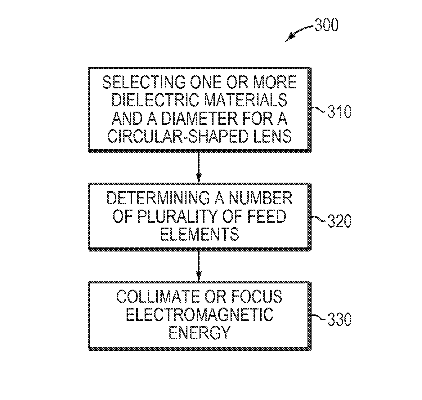
[0010]In one aspect, the invention features an antenna. The antenna includes a circular-shaped lens disposed within a volume that has a first surface, a second surface, and a center, the circular-shaped lens having an axis of rotation that passes substantially through the first surface, the second surface and the center. The antenna also includes a plurality of feed elements positioned at a plurality of focal points of the circular-shaped lens along at least a portion of a circle that is centered substantially on the axis of rotation. The antenna also includes a thickness of ⅓ or less of a diameter of the antenna.
[0011]In some embodiments, each feed element is positioned 180 degrees or substantially 180 degrees from a corresponding feed element of the plurality of feed elements. In some embodiments, one or more of the plurality of feed elements transmits electromagnetic energy to the circular-shaped lens and the circular-shaped lens collimates at least a portion of the transmitted electromagnetic energy.
[0012]In some embodiments, the antenna includes a switching element in electrical communication with the plurality of feeds, the switching element selects the one or more of the plurality of feed elements to transmit electromagnetic energy such that the transmitted electromagnetic energy has a maximum radiation in a desired direction. In some embodiments, the antenna includes a switching element in electrical communication with the plurality of feeds, and the switching element selects the one or more of the plurality of feed elements to receive electromagnetic energy from a desired direction.
Problems solved by technology
A large height can be problematic where height is limited, such as tunnels, underpasses, under bridges, in parking garages, or driving under branches.
In addition, increased height can increase fuel consumption for commercial and military vehicles and aircraft due to added wind resistance.
A large height can also increase visibility of the antenna platform, which is problematic for some applications (e.g., military vehicles) where low visibility of the platform is desirable.
A large height can also reduce the mission range due to air resistance.
In addition to size limitations, reflector and horn antennas typically limit the number of simultaneous beams and links because they typically only radiate in one direction at a time.
Narrow-beam antennas such as many reflector antennas can require accurate mechanical steering of the dish, which is slow and greatly reduces the ability to operate on-the-move for off-road vehicles in rough terrain.
Fixed beam antennas can have a lack of beam agility, resulting in loss of link when a platform the antenna is deployed upon rolls or turns.
Phased array antennas can be extremely expensive, can have high weight cooling systems, can operate over a limited frequency bandwidth with a limited number of simultaneous beam directions, and can have difficulty forming a beam at very low elevation angles unless they include a large vertical aperture.
Existing designs incorporating lenses also have many of the same limitations and problems as phased arrays, or are too large and heavy for practical use.
Method used
Image
Click on the blue label to locate the original text in one second.
Reading with bidirectional positioning of images and text.
Examples
Embodiment Construction
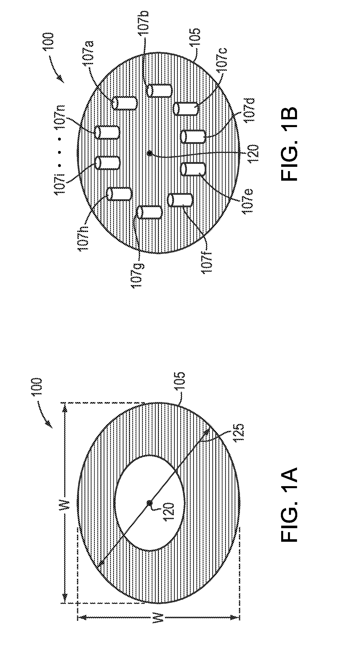
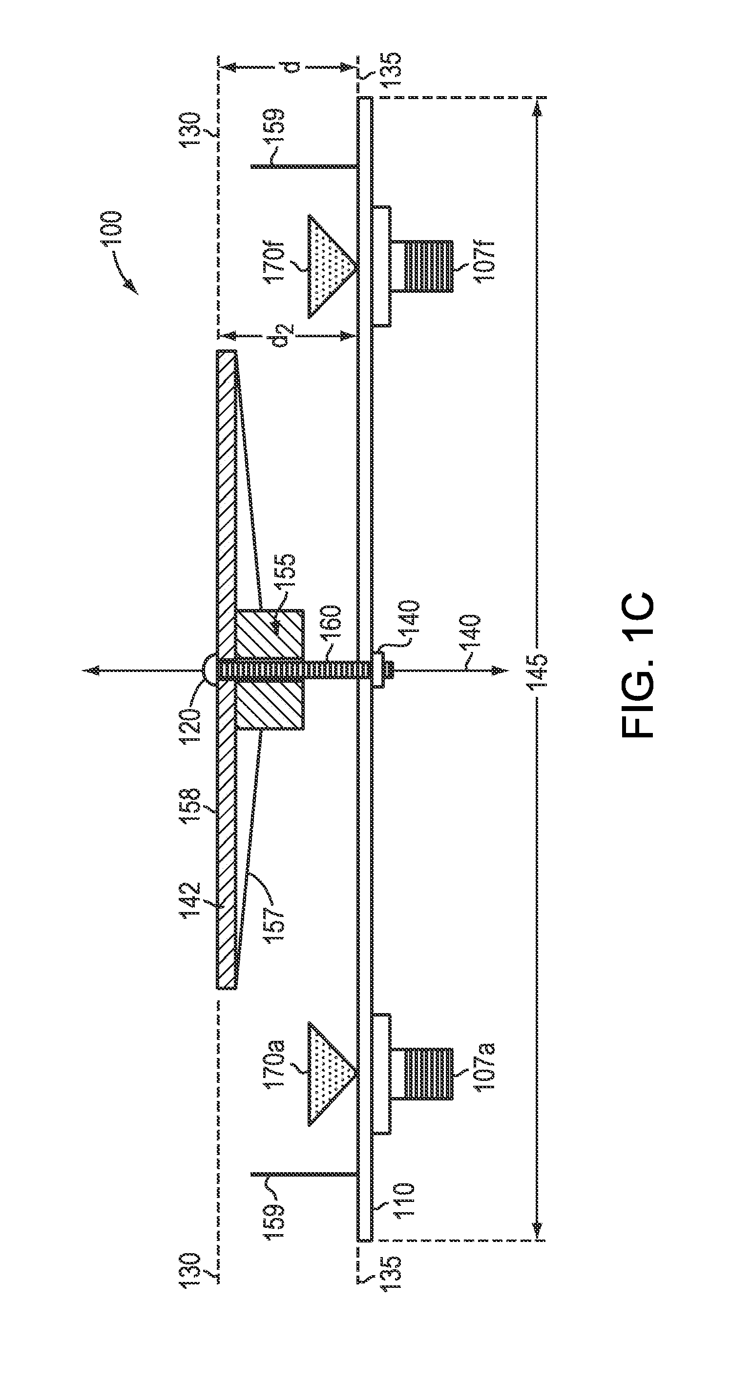
[0026]FIG. 1A is a diagram showing a top down view of an antenna 100, according to an illustrative embodiment of the invention. FIG. 1B is a diagram showing a bottom up view of the antenna of FIG. 1A, according to an illustrative embodiment of the invention. FIG. 1C is a diagram showing a cross-sectional view of the antenna of FIG. 1A, according to an illustrative embodiment of the invention. The following discussion refers to elements shown in FIG. 1A, FIG. 1B, and FIG. 1C.
[0027]The antenna 100 includes a circular-shaped lens 105, a plurality of feed elements 170a, 170f, . . . , 170n, generally, 170. In some embodiments, the antenna 100 includes a mounting plate 110. In some embodiments, the antenna 100 weighs 259 grams.
[0028]The circular-shaped lens 105 includes a center 120, a diameter 125, and an axis of rotation 140. The circular-shaped lens 105 is disposed within a volume that includes a width w, a depth d, a first surface 130, and a second surface 135. The width w is substant...
PUM
Abstract
An antenna is provided for transmitting and receiving electromagnetic energy. A circular-shaped lens is disposed within a volume that has a first surface, a second surface, and a center, has an axis of rotation that passes substantially through the first surface, the second surface and the center. A plurality of feed elements are positioned at a plurality of focal points of the circular-shaped lens along at least a portion of a circle which is centered substantially on the axis of rotation. The thickness of the antenna is ⅓ or less of the diameter of the antenna.
Description
CROSS REFERENCE TO RELATED APPLICATION[0001]This application claims the benefit of and priority to U.S. Provisional Patent Application No. 61 / 350,800, filed Jun. 2, 2010, the entire disclosure of which is incorporated herein by reference.FIELD OF THE INVENTION[0002]The present invention relates to a low-profile multiple-beam antenna having a wide field of view.BACKGROUND[0003]Communication systems that include antennas can be deployed in a variety of ways. For example, atop cars, trucks, trains, recreational vehicles (RVs), boats, military vehicles such as High Mobility Multipurpose Wheeled Vehicles (HMMWV), commercial aircraft, unmanned aerial vehicles (e.g., Global Hawk), as part of satellites, or networks (e.g., commercial WIMAX, WIFI, or the Army's Warfighter Information Network-Tactical program). Many existing communications systems that operate at C, X, Ku, or Ka-bands use specific types of antennas, for example, reflector (dish) antennas, horn antennas, and / or fixed-beam ante...
Claims
Application Information
Patent Timeline
Application Date:The date an application was filed.
Publication Date:The date a patent or application was officially published.
First Publication Date:The earliest publication date of a patent with the same application number.
Issue Date:Publication date of the patent grant document.
PCT Entry Date:The Entry date of PCT National Phase.
Estimated Expiry Date:The statutory expiry date of a patent right according to the Patent Law, and it is the longest term of protection that the patent right can achieve without the termination of the patent right due to other reasons(Term extension factor has been taken into account ).
Invalid Date:Actual expiry date is based on effective date or publication date of legal transaction data of invalid patent.

