
Liquid discharger and image forming apparatus having the same

a technology of liquid discharger and image forming apparatus, which is applied in the direction of printing and other printing apparatus, can solve the problems of low printing quality, increased late sheet reaching the inkjet head, etc., and achieves the effect of increasing the size and cost of inkjet printer and low printing quality

Active Publication Date: 2014-05-27
BROTHER KOGYO KK
View PDF10 Cites 0 Cited by
  • Summary
  • Abstract
  • Description
  • Claims
  • Application Information

AI Technical Summary

Benefits of technology

The invention provides techniques to improve printing quality and accuracy when liquid is discharged onto a sheet of paper. The technique involves detecting the position of the sheet of paper between the pressing roller and the inkjet head, and adjusting the time when the first liquid is discharged to prevent delay caused by bending and slipping of the sheet. This helps to ensure that the droplets of liquid land in the desired position, resulting in high printing quality. The use of sensors and increased size and cost of the inkjet printer are avoided by the techniques presented in this patent.

Problems solved by technology

In the aforementioned technique, when a leading end of the conveyed sheet collides against the pressing roller, the sheet might be bent and slip on the pressing roller, and thereby it might cause delay relative to an estimated sheet feeding time to be taken for feeding the sheet to an inkjet head.
When the delay is caused relative to the estimated sheet feeding time, the sheet reaches the inkjet head late by the delay.
Hence, when a droplet of ink is discharged at a moment originally set based on the estimated sheet feeding time, the droplet of ink lands in a different position from a desired position (in which the droplet of ink is to land) on the sheet, and it leads to a low level of printing quality.
However, the incorporation of the sensor results in increased size and cost of the inkjet printer.

Method used


Image

  • Liquid discharger and image forming apparatus having the same
  • Liquid discharger and image forming apparatus having the same
  • Liquid discharger and image forming apparatus having the same

Examples


Embodiment Construction

[0017]It is noted that various connections are set forth between elements in the following description. It is noted that these connections in general and, unless specified otherwise, may be direct or indirect and that this specification is not intended to be limiting in this respect.

[0018]Hereinafter, an embodiment according to aspects of the present invention will be described with reference to the accompanying drawings.

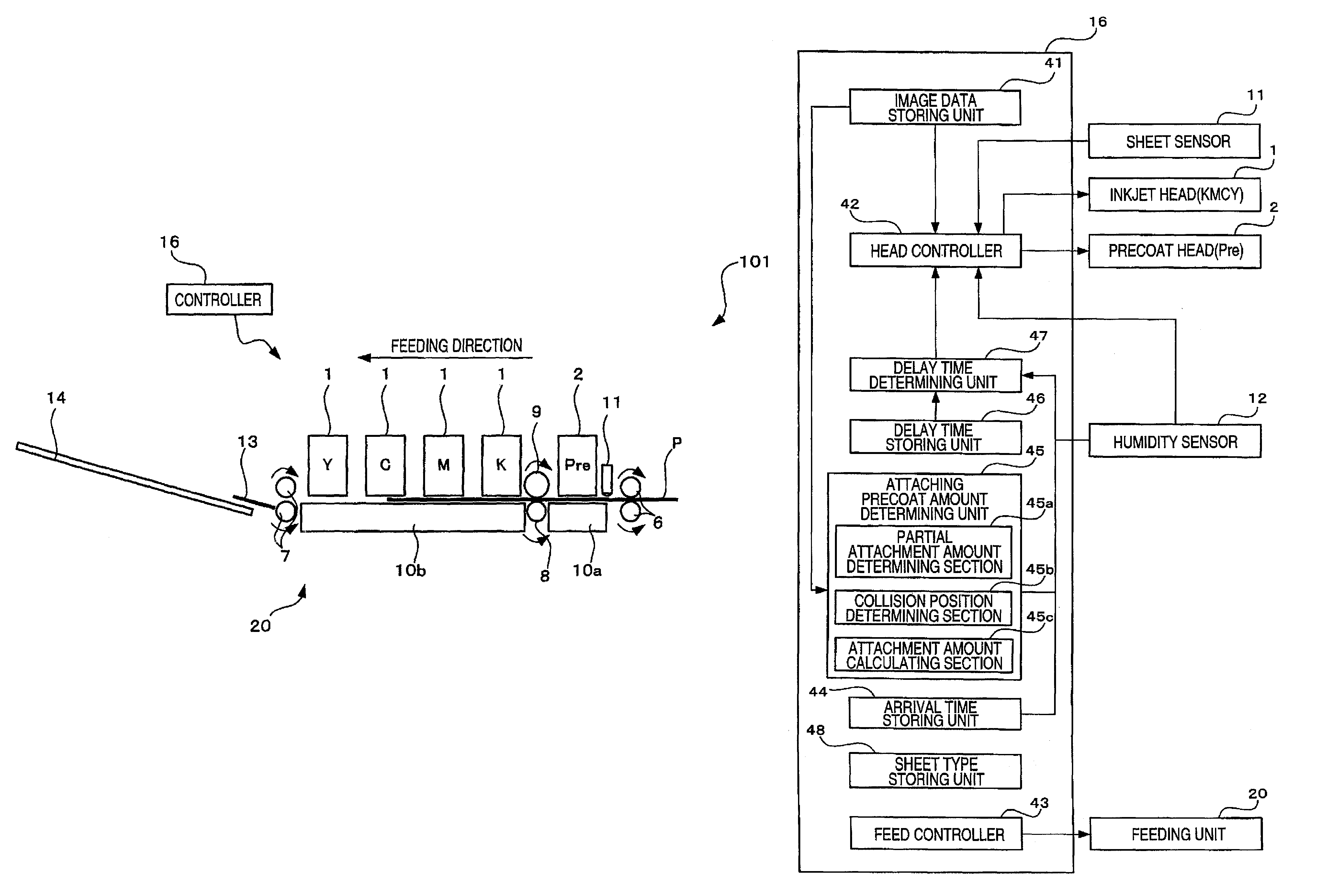
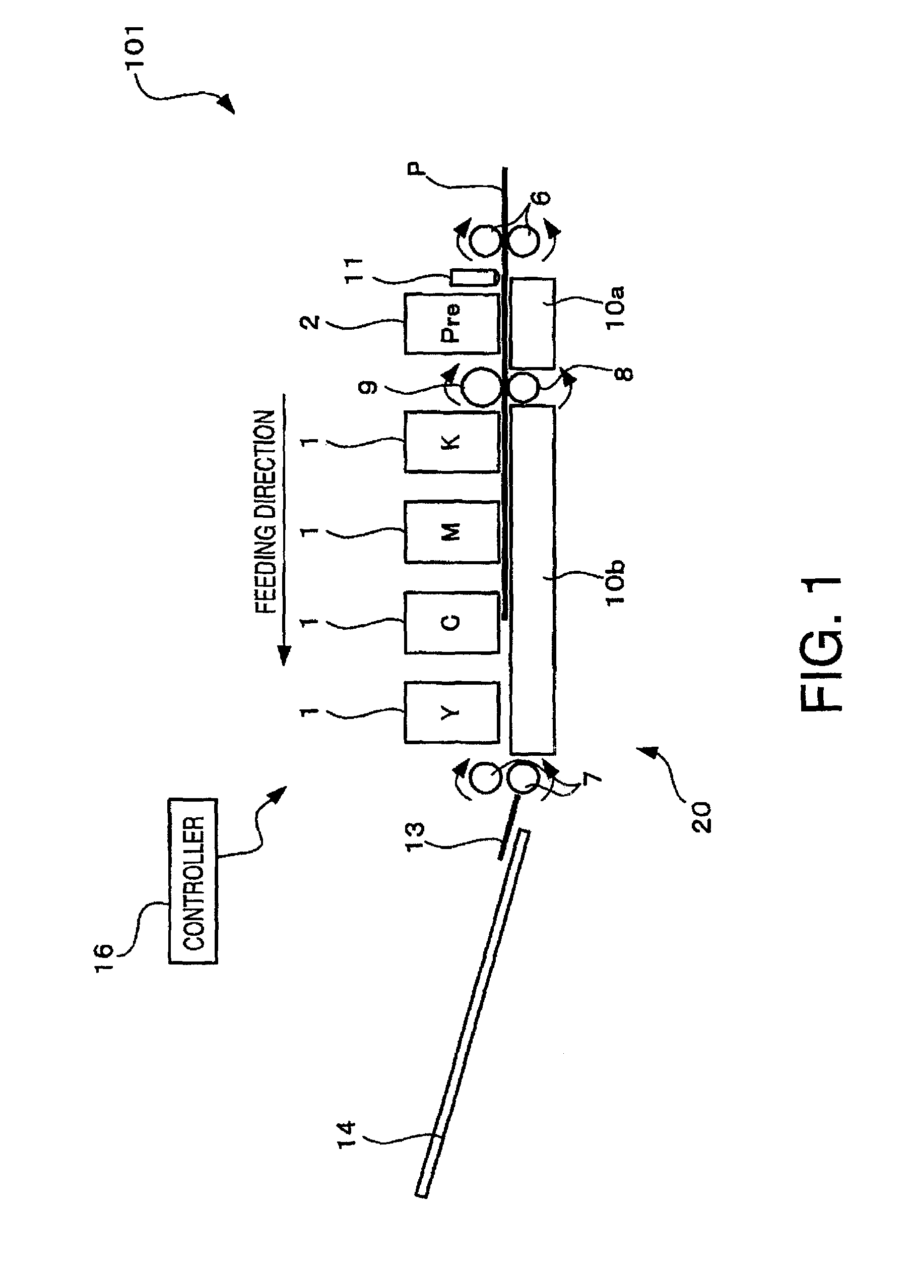
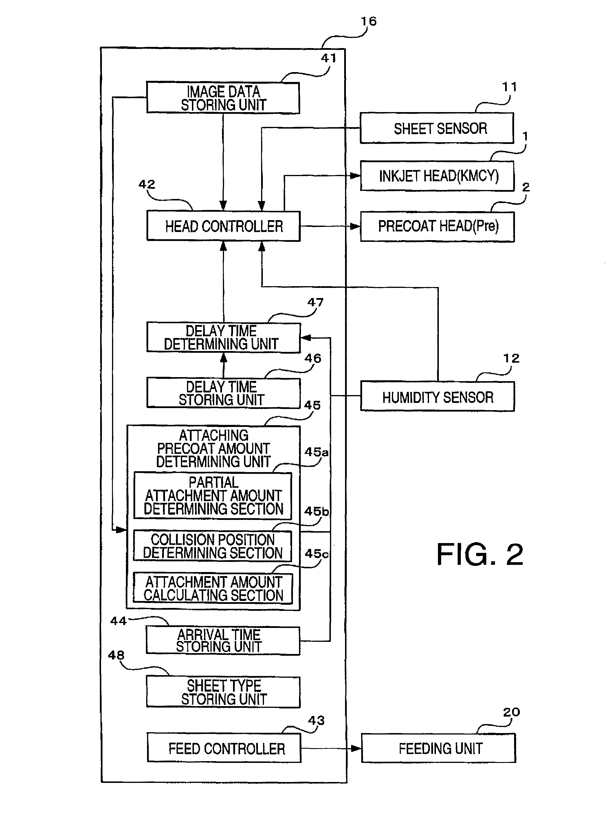
[0019]As shown in FIG. 1, an inkjet printer 101 includes a feeding unit 20 configured to feed a sheet P, four inkjet heads 1 configured to discharge ink droplets of respective colors black (K), magenta (M), cyan (C), and yellow (Y), a precoat head 2 configured to discharge a droplet of precoat liquid (Pre) for agglutinating or precipitating a coloring component of each color of ink, a sheet sensor 11, and a controller 16 configured to control the inkjet printer 101 as a whole. It is noted that in the embodiment, an auxiliary scanning direction is a direction paralle...


PUM


Abstract

A liquid discharger is provided that includes a sheet detector, a second discharging head discharging second liquid, a rotary roller, and a first discharging head discharging first liquid disposed in the above order from an upstream side in a feeding direction. The liquid discharger further includes an arrival time storing unit storing a standard arrival time for the predetermined position of a sheet to reach the first discharging head from the sheet detector when there is no second liquid attaching onto the rotary roller, a delay time storing unit storing a relationship between a attachment amount and a delay time, a delay time determining unit determining a delay time corresponding to a determined attachment amount based on the relationship, and a controller determining a moment when the first discharging head is to discharge the first liquid based on the stored standard arrival time and the determined delay time.

Description

CROSS-REFERENCE TO RELATED APPLICATION[0001]This application claims priority under 35 U.S.C. §119 from Japanese Patent Application No. 2010-194808 filed on Aug. 31, 2010. The entire subject matter of the application is incorporated herein by reference.BACKGROUND[0002]1. Technical Field[0003]The following description relates to one or more techniques to, prior to discharging a droplet of first liquid, discharge onto a recording medium second liquid for agglutinating or precipitating one or more components contained in the first liquid.[0004]2. Related Art[0005]An inkjet printer has been known, which is configured to, prior to discharging a droplet of ink to form a dot onto a sheet, discharge pretreatment liquid for agglutinating or precipitating one or more coloring components contained in the ink, onto an area where the dot is to be formed, in order to restrain bleeding of the dot on the sheet. For the inkjet printer, a technique has been known that is to press and spread the discha...

Claims


Application Information

Patent Timeline
Patent Type & Authority Patents(United States)
IPC IPC(8): B41J29/38
CPCB41J2/2114
Inventor UCHINO, SHUNJI
Owner BROTHER KOGYO KK
Learn More