Optical image measurement apparatus and optical image measurement method

a technology of optical image and measurement apparatus, which is applied in the field of optical image measurement apparatus and optical image measurement method, can solve the problems that the typical oct that measures the reflectance distribution cannot visualize birefringence, and achieve the effects of suppressing and increasing the size and cost of the apparatus

Active Publication Date: 2018-05-03
HITACHI-LG DATA STORAGE
View PDF6 Cites 2 Cited by
  • Summary
  • Abstract
  • Description
  • Claims
  • Application Information

AI Technical Summary

Benefits of technology

[0011]The polarization sensitive optical image measurement apparatus described in Patent Document 2 attempts to acquire Jones vector of the sample by a single scan using an EO modulator. However, typical EO modulators are large and expensive. Thus it results in increased size and cost of the apparatus.
[0012]Exemplary embodiments relate to providing an optical image measurement apparatus that is capable of acquiring information on birefringence of a sample while suppressing size and cost of the apparatus.
[0013]In the present disclosure: second measurement light different from first measurement light is generated using a passive optical element that generates light of second polarization state different from first polarization state; a time when the first measurement light is irradiated onto a sample is adjusted at a first time, and a time when the second measurement light is irradiated onto the sample is adjusted at a second time different from the first time. First and second signal light that are acquired from the sample reflecting or scattering the first and the second measurement light are detected and then are outputted in a form of an electric signal. Thereby it is possible to acquire information corresponding to different polarization states simultaneously by a single scan. Accordingly, it is possible to acquire more information on birefringence of the sample than conventional techniques with inexpensive and simple configurations. The passive optical element is an optical element that does not require some electrical / magnetic / mechanical controls for performing the element's functionalities.
[0014]An example of the present disclosure includes a light shield that shields the first and the second measurement light. A time when the light shield shields the first measurement light and a time when the light shield shields the second measurement light are adjusted, thereby the first and the second times are adjusted. Since the light shield controls irradiation timings of the measurement light, it is beneficial in that it is not necessary to provide multiple light sources for generating the first and the second measurement light.
[0015]An example of the present disclosure includes a first and a second light sources. Light emitted from the first light source is irradiated onto the sample as the first measurement light, and light emitted from the second light source is irradiated onto the sample as the second measurement light. A time when the first light source emits light and a time when the second light source emits light are controlled, thereby the first and the second times are controlled. Since the irradiation timing of the measurement light may be controlled by controlling the light-emitting timings of the light sources, it is possible to rapidly control the irradiation timings with simple configurations.

Problems solved by technology

However, typical OCT that measures reflectance distribution cannot visualize birefringence.

Method used


Image

  • Optical image measurement apparatus and optical image measurement method
  • Optical image measurement apparatus and optical image measurement method
  • Optical image measurement apparatus and optical image measurement method

Examples


embodiment 1

eory of Optical System

[0047]Hereinafter, the operation theory and the effect of the optical image measurement apparatus according to the embodiment 1 will be described in details using equations. The Jones matrix of the sample and the Jones vectors of the first and the second measurement light are described by Equations 1-3 below.

[Equation1]R=(rpprpsrsprss)(1)[Equation2]Eprob,1=2(Eprob0)(2)[Equation3]Eprob,2=2(0Eprob)(3)

[0048]The Jones vectors of the first and the second signal light after passing through the polarization beam splitter 114 are described by Equations 4 and 5 below.

[Equation4]Esig,1=(rpprsp)Eprob(4)[Equation5]Esig,2=(rpsrss)Eprob(5)

[0049]If the Jones vectors of the first and the second reference light are described by Equations 6 and 7 below, the Jones vectors of the first to fourth multiplexed light are given by Equations 8-11 below.

[Equation6]Eref,1=(11)Eref(6)[Equation7]Eref,2=(1-1)Eref(7)[Equation8]E1=(rppEprobEref)(8)[Equation9]E2=(ErefrspEprob)(9)[Equation10]E3=...

embodiment 1 summary

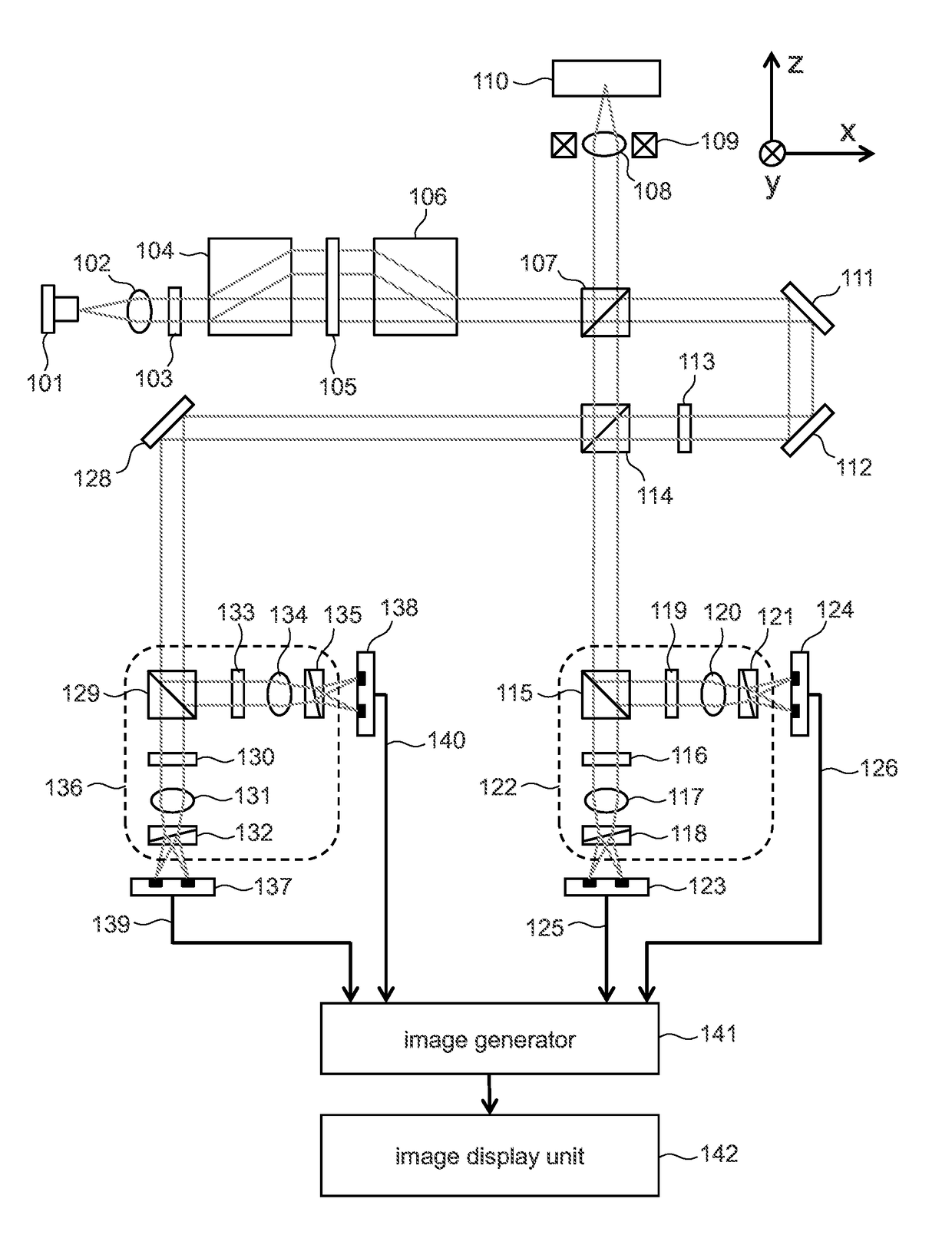
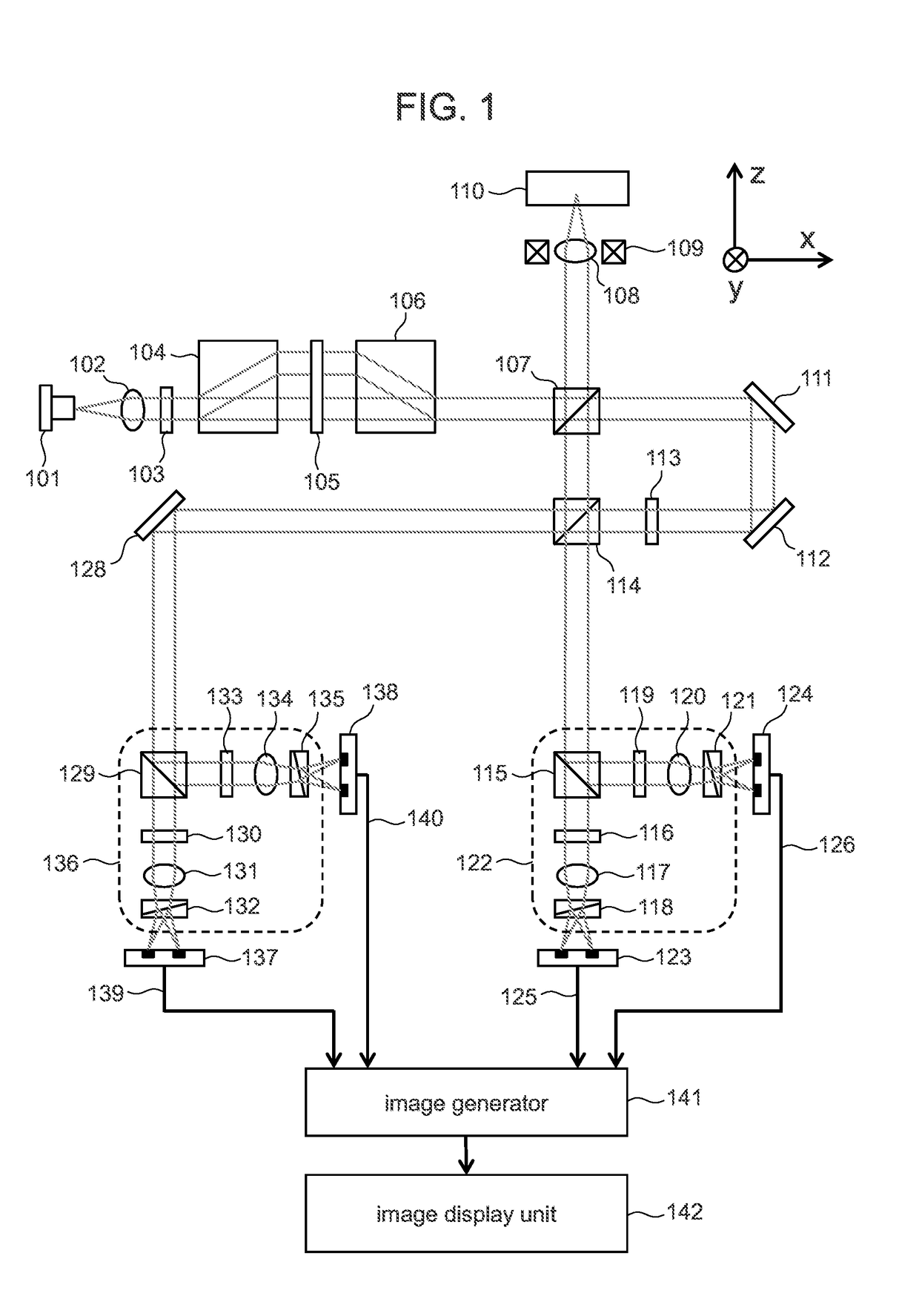
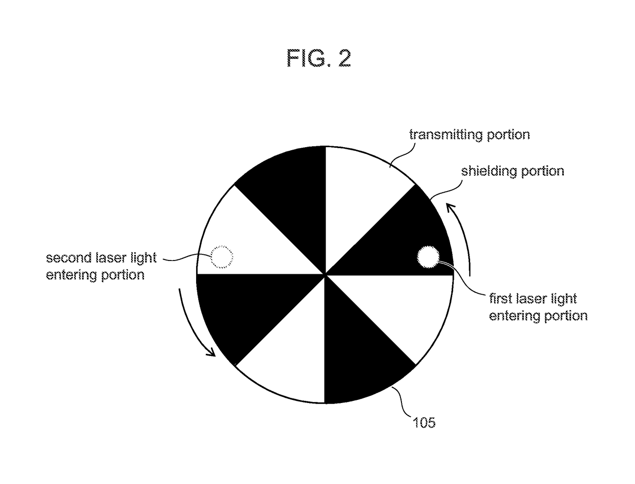
[0056]The optical image measurement apparatus according to the embodiment 1: generates the first and the second measurement light with different polarization states using the beam displacer 104, the beam displacer 104 being a passive optical element; and irradiates these measurement light alternately using the light shielding element 105 (irradiation time controller). Accordingly, it is possible to calculate the Jones matrix of the sample 110 by fewer scan (one scan) than conventional techniques without using large and expensive polarization modulation elements.

embodiment 2

[0057]FIG. 4 is a schematic diagram of a configuration example of the optical image measurement apparatus according to an embodiment 2 of the present disclosure. Same reference signs are assigned to same components as in FIG. 1, and explanations thereof will be omitted. The optical image measurement apparatus according to the embodiment 2 is different from the embodiment 1 in that two different light sources are employed. Further, the embodiment 2 is different from the embodiment 1 in that a single interference optical system is used to detect each measurement light. Other configurations are generally same as in the embodiment 1. Thus the differences will be mainly described below.

[0058]The first laser light in P polarization state emitted from the first light source 401 is converted into parallel light by a collimate lens 402. The parallel light enters a polarization beam splitter 403. The second laser light in P polarization state emitted from a second light source 404 is converte...


PUM


Abstract

Exemplary embodiments relate to providing an optical image measurement apparatus that is capable of acquiring information on birefringence of a sample while suppressing size and cost of the apparatus. In the present disclosure: second measurement light different from first measurement light is generated using a passive optical element that generates light of second polarization state different from first polarization state; a time when the first measurement light is irradiated onto a sample is adjusted at a first time, and a time when the second measurement light is irradiated onto the sample is adjusted at a second time different from the first time.

Description

CROSS REFERENCE TO RELATED APPLICATIONS[0001]The present application claims priority from Japanese patent application JP 2016-210709 filed on Oct. 27, 2016, the content of which is hereby incorporated by reference into this application.BACKGROUNDTechnical Field[0002]The present disclosure relates to a technique for observing samples using light.Background Art[0003]Optical Coherence Tomography (OCT) is a technique that acquires tomographic images of samples using interference of light. OCT has been in practical use from the year 1996 in the field of funduscopy. In recent years, it has been studied to apply OCT into various fields such as cardiology, odontology, oncology, food industry, or regenerative medicine.[0004]In OCT technology, light from a light source is divided into two light, i.e. signal light that is irradiated onto the sample and reference light that is reflected by a reference light mirror. Measurement signals are acquired by causing the signal light reflected from the ...

Claims


Application Information

Patent Timeline
Patent Type & Authority Applications(United States)
IPC IPC(8): G01B9/02
CPCG01B9/02011G01B9/02091G01B9/02041G01N21/23G01B2290/70G01B2290/45
Inventor OSAWA, KENTARO
Owner HITACHI-LG DATA STORAGE
Why Eureka
Try Eureka