Automatic exposure control for flash photography

a technology of automatic exposure control and flash photography, applied in the field of flash photography, can solve the problems of subject detail loss in the underexposed and overexposed areas of the captured image, light areas to be overexposed in the captured image, and dark areas to be underexposed in the final image,

Inactive Publication Date: 2014-05-27
INT BUSINESS MASCH CORP
View PDF25 Cites 41 Cited by
  • Summary
  • Abstract
  • Description
  • Claims
  • Application Information

AI Technical Summary

Problems solved by technology

However, if a photographic subject includes a high proportion of relatively dark areas, adjusting the flash output according to an 18% gray average tonal value may cause light areas to be overexposed in the captured image.
Conversely, if the photographic subject includes a high proportion of relatively light areas, dark areas may be underexposed in the final image.
Subject detail may be lost in underexposed and overexposed areas of a captured image.
The larger the uncertainty in measured distances, the greater the difficulty flash units with AFEC may have in predicting correct flash settings for achieving a desired range of tonal values in a captured image.
However, precise compensation of bounce flash settings for a flash unit with AFEC is difficult partly because of the difficulty in measuring flash-to-subject distance, but also for other reasons such as color shifts and reflectivity of the surface from which light is bounced.
Inaccurate compensation of bounce flash settings prevents accurate prediction of tonal values in the resulting image.
However, bracketing may be inappropriate, distracting, or impractical depending on the photographic subject and its location.
Camera histograms can be used to predict how much a change in flash settings or camera settings will affect a captured image, but it can be very difficult to associate a particular feature of a photographic subject with a particular point on a histogram plot, so predicting a change in the image of that feature can also be very difficult, especially for photographic subjects that comprise multiple tonal values for each feature of the subject.
Flash units with AFEC systems which produce acceptable image results in direct flash photography may produce poor image results, for example loss of subject detail in highlight or shadow areas, when the AFEC system is allowed to control flash settings during bounce flash photography.

Method used


Image

  • Automatic exposure control for flash photography
  • Automatic exposure control for flash photography
  • Automatic exposure control for flash photography

Examples


Embodiment Construction

[0024]The following description is made for the purpose of illustrating the general principles of the invention and is not meant to limit the inventive concepts claimed herein. Further, particular features described herein can be used in combination with other described features in each of the various possible combinations and permutations. Unless otherwise specifically defined herein, all terms are to be given their broadest possible interpretation including meanings implied from the specification as well as meanings understood by those skilled in the art and / or as defined in dictionaries, treatises, etc.

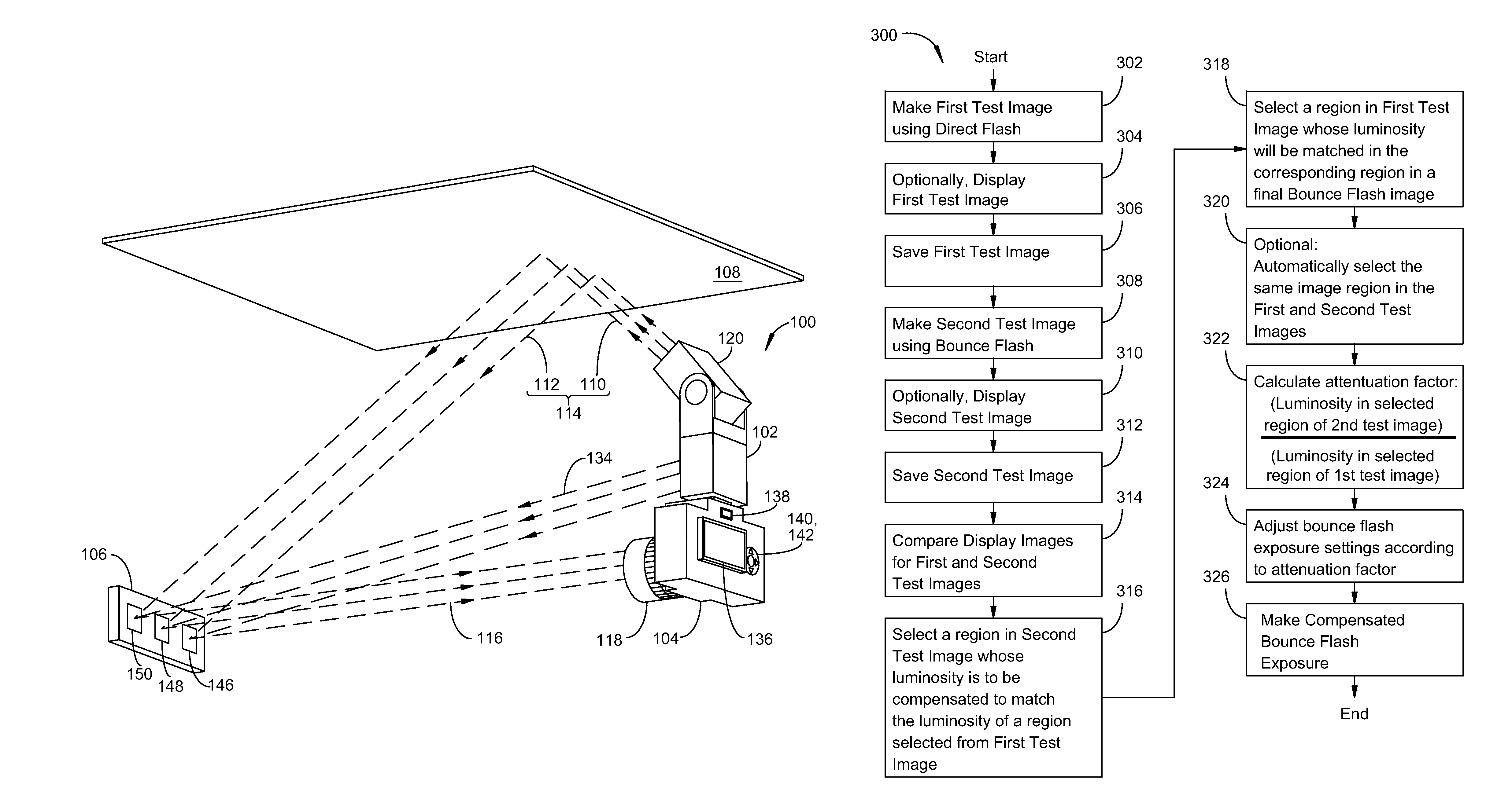
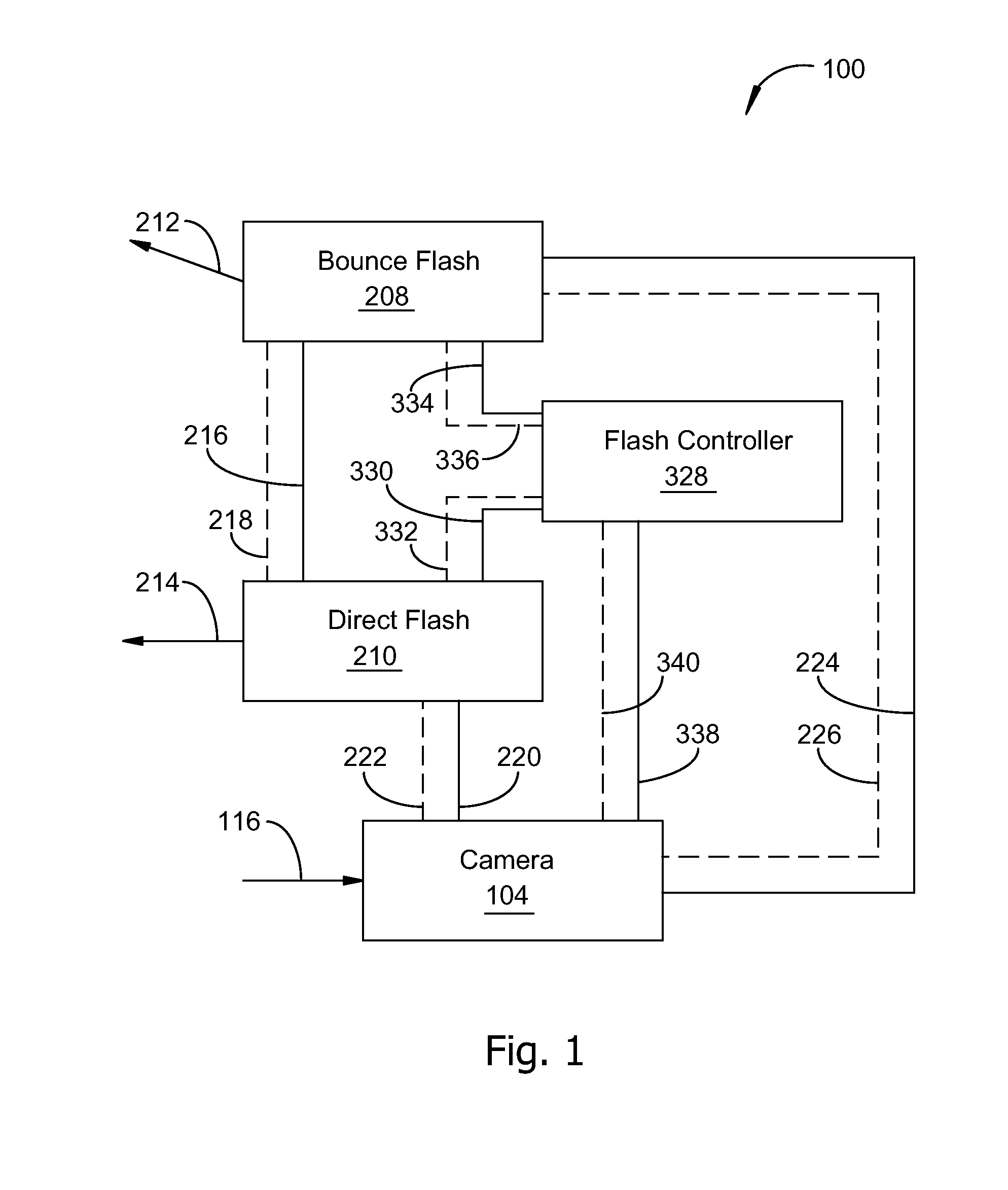
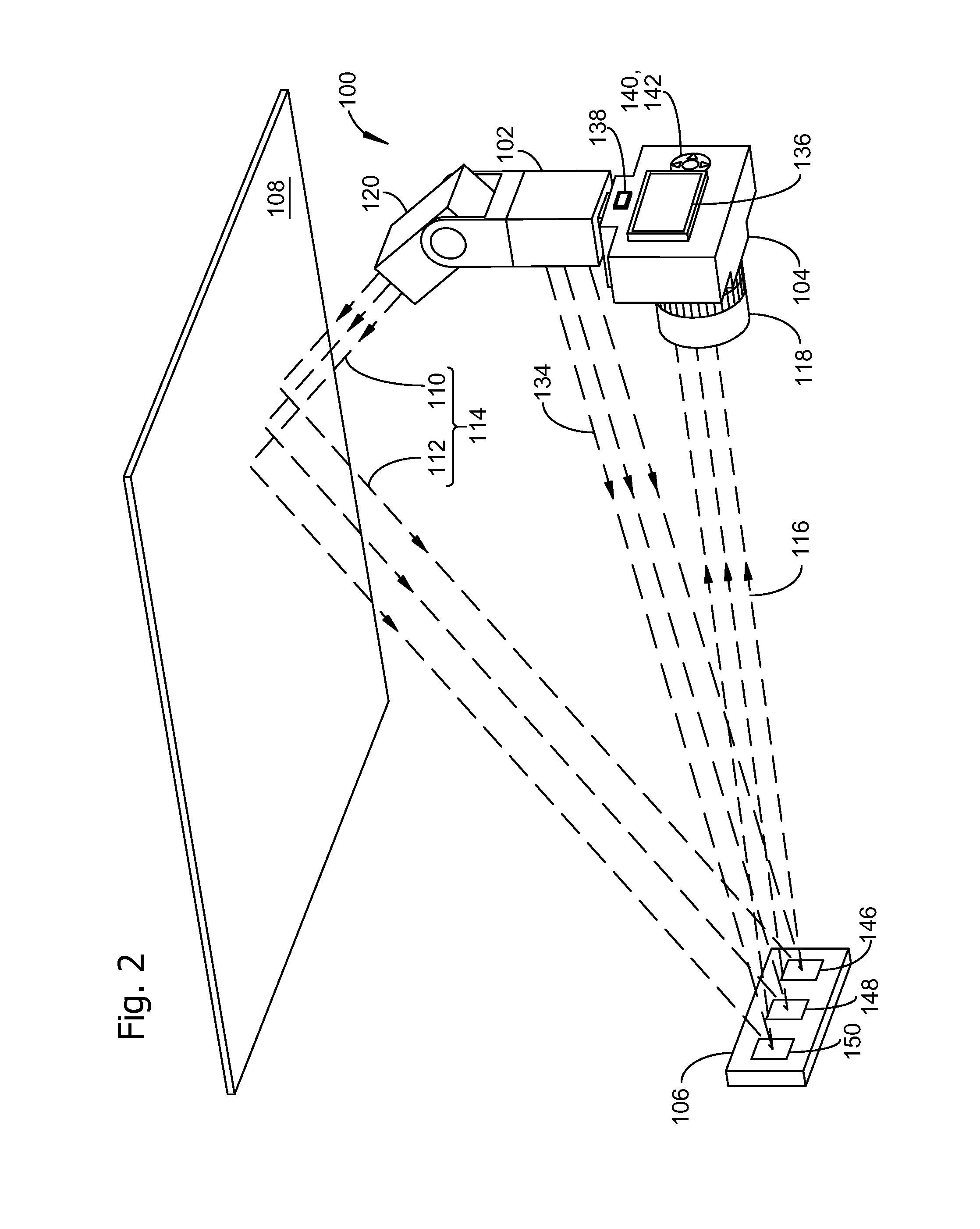
[0025]Some embodiments of the invention comprise a flash unit adapted for matching a value of luminosity representing a selected region of an image captured during bounce photography to a value of from luminosities from corresponding regions in a direct flash test image and a bounce flash test image. Some embodiments of the invention comprise a combination of a camera and a flash u...


PUM


Abstract

A photographic flash unit comprises a direct flash unit and a bounce flash unit rotatably connected to the direct flash unit. Status and control lines coupled between a hot shoe and each flash unit enable independent triggering and control of each flash unit. The direct and bounce flash units may be a part of a digital camera adapted to make a first test exposure using direct flash illumination and second test exposure using bounce flash illumination, then computing an attenuation factor for compensating a selected flash exposure parameter by dividing the selected parameter by the attenuation factor. Steps in a method embodiment include making a first test image, making a second test image, selecting regions in the first and second test images, computing an attenuation factor from luminosity values for the first and second test images, and compensating settings for a final bounce flash image by the attenuation factor.

Description

BACKGROUND[0001]The present invention relates generally to flash photography, and more particularly to flash compensation for bounce illumination.[0002]A flash unit outputs a controlled pulse of light in response to a trigger signal received from a camera, another flash unit, or other control device. A flash unit may be mechanically attached to a camera for primary or supplemental illumination of a photographic subject. One or more flash units may be positioned some distance away from the camera in addition to, or alternatively instead of, a flash unit mechanically attached to a camera. Each of the flash units receives a signal from the camera, or optionally from other flash units or control devices, for initiating and terminating light output. Light from the one or more flash units reflects from a photographic subject and the reflected light is collected by a camera lens for forming a photographic image. Controlling the light output from a flash unit, referred to as flash exposure ...

Claims


Application Information

Patent Timeline
Patent Type & Authority Patents(United States)
IPC IPC(8): G03B15/03H04N9/73H04N5/222G03B15/06H04N5/228
CPCH04N5/2354G03B2215/0521G03B15/05G03B2215/0553H04N9/73H04N23/74
Inventor SPIELBERG, ANTHONY, C.
Owner INT BUSINESS MASCH CORP
Why Eureka
Try Eureka