Light emitter

Inactive Publication Date: 2012-01-12
KURARAY CO LTD
View PDF2 Cites 37 Cited by
  • Summary
  • Abstract
  • Description
  • Claims
  • Application Information

AI Technical Summary

Benefits of technology

[0015]According to an aspect of the light emitter of the present invention, it is possible to ensure transparency by lowering the haze value in the thickness direction or diameter directi

Problems solved by technology

Therefore, in either of the case, it has been non-transparent as the whole display device.
Therefore, although it is possible to perfo

Method used


Image

  • Light emitter
  • Light emitter
  • Light emitter

Examples


first exemplary embodiment

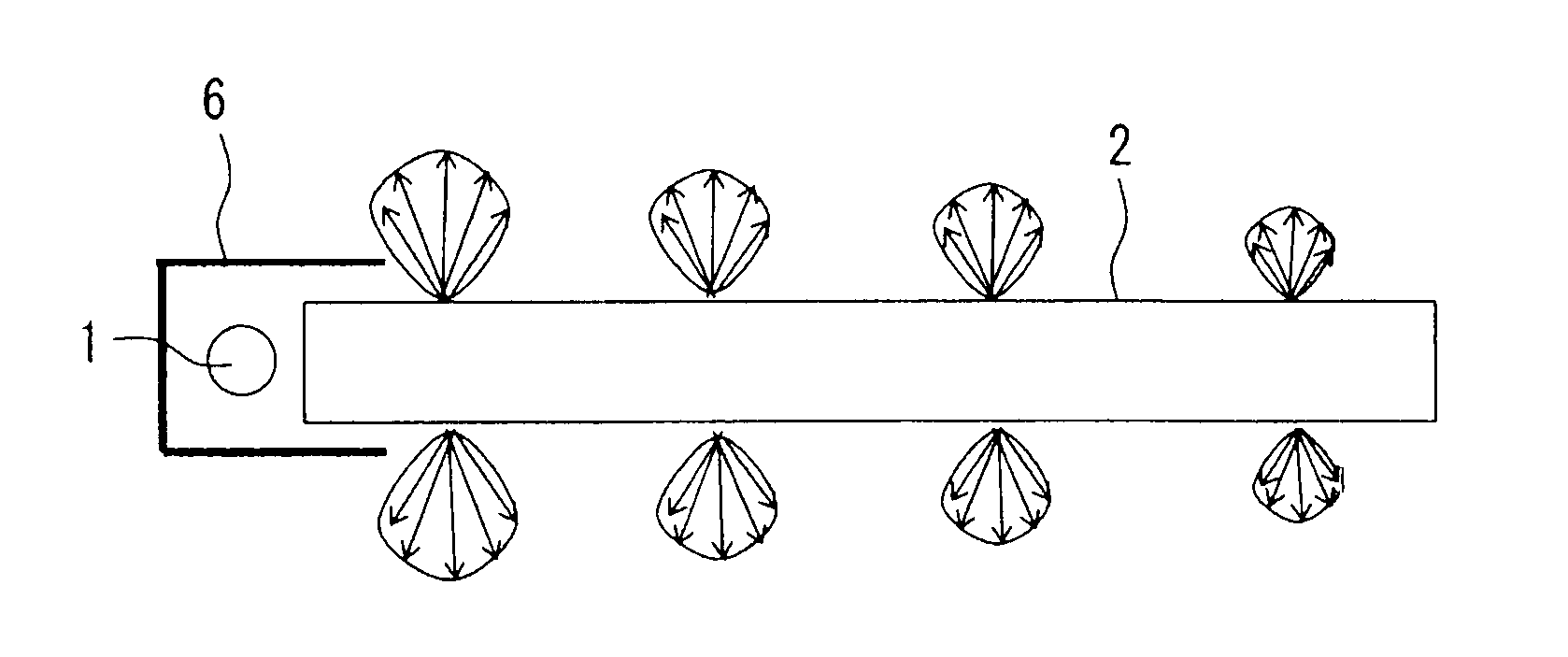
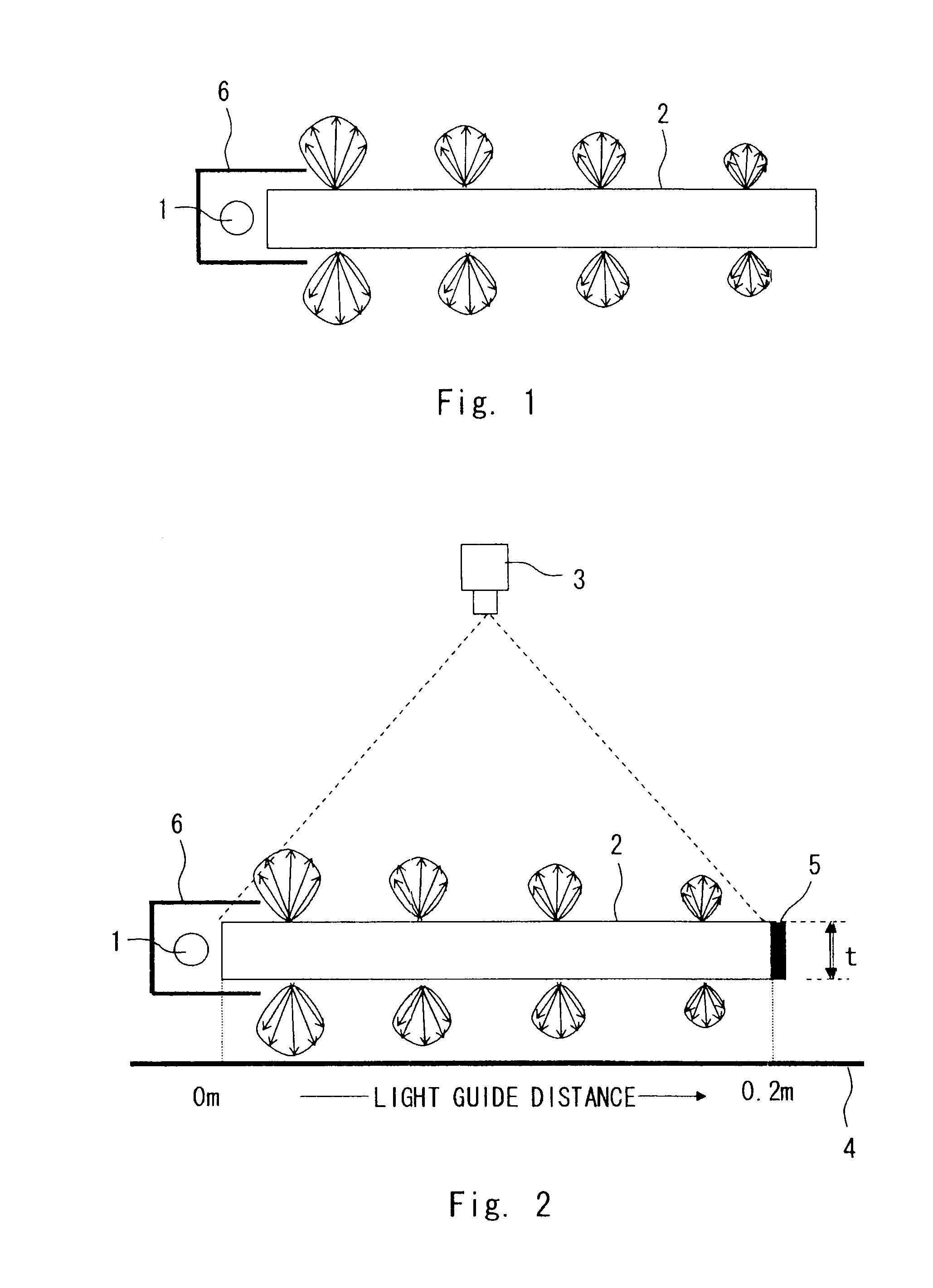
[0030]Hereinafter, as for a first exemplary embodiment of the present invention, a plate-shaped surface light emitter is explained as an example of a light emitter. The surface light emitter according to the first exemplary embodiment of the present invention uses a light guide including light diffusing particles. When light is supplied from a light source, the light guide guides the light in the length direction of the light guide while scattering the light in the thickness direction of the light guide. The length direction of the light guide is a direction to an opposing end surface from an end surface (incident end surface) for supplying the light from the light source, and is parallel to a direction in which the supplied light-guiding light travels in a straight line. The thickness direction of the light guide is a direction to indicate the thickness of the light guide, and is perpendicular to the length direction. Further, the direction perpendicular to both of the length direc...

second exemplary embodiment

[0073]The first exemplary embodiment explained the plate-like surface light emitter as an example of the light emitter. A second exemplary embodiment explains the case of other shapes of the light emitter. An example of the light emitter of this exemplary embodiment is explained using FIGS. 8A to 8D and 9.

[0074]As for the shape of the surface light emitter, which is one exemplary embodiment of the light emitter, other than the light emitter 7a such as a rectangle as in FIG. 8A, the shape viewed from the front surface may be polygons including a rectangle, a trapezoid, and a triangle, or shapes formed by curves including a circle and an ellipse. Additionally, the surface light emitter may be a wing-shaped light emitter 7b (FIG. 8B), a frame-shaped light emitter 7c (FIG. 8C), or other shapes formed by curves and straight lines.

[0075]Moreover, the surface light emitter is not limited to the plate shape as shown in FIGS. 8A to 8C, but may be bent as shown in FIG. 8D. In FIG. 8D, a line ...

example

Example 1

[0095]Examples and comparative examples are shown below. The surface light emitter was manufactured using an injection molding machine. Common conditions for the example and the comparative example are shown below.

[0096]Base resin: PMMA (acrylic resin) (“Parapet” manufactured by Kuraray Co., Ltd.)[0097]Refractive index: 1.494 (nD)[0098]Sample size: 5 mm thickness×Light guide length 200 mm×width 70 mm[0099]Light source used: “LED NFSW036BT” manufactured by Nichia Corporation[0100]Number of usage: Seven[0101]Spacing: 10 mm[0102]Applied voltage: 2.8 V / one light source[0103]The size of one light source: 3 mm (light emitting unit)

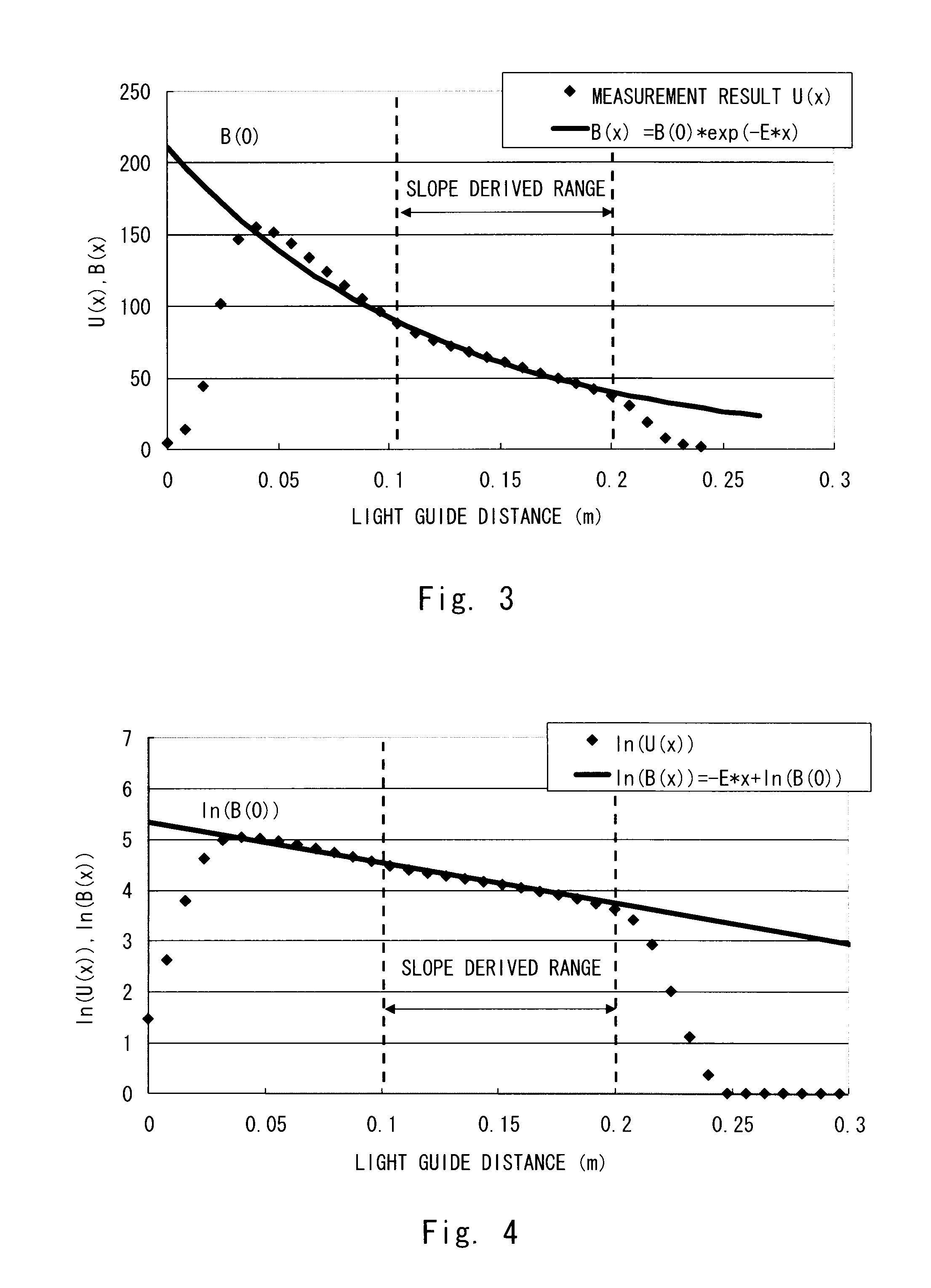
[0104]The material configuration and measurement result of the example and the comparative example are shown in Table 1. The relationship between the luminance attenuation coefficient E(m−1) and the haze value per 5 mm thickness is shown in FIG. 10. The haze value of the horizontal axis is the haze value per 5 mm thickness as mentioned above. From the m...


PUM


Abstract

Provided is a surface light emitter that supplies light using a light guide method, and ensures transparency by lowering a haze value in a thickness direction at the time when a light source is turned off, and enables highly efficient light emission by using plate-surface transversal radiant emitted light at the time when the light source is on. A surface light emitter (2) including light diffusing particles guides light in a length direction of the light guide while scattering the light in the thickness direction of the light guide while scattering the light in the thickness direction of the light guide, and a calculated value (m−1/%) obtained by dividing a luminance attenuation coefficient E (m−1) by a haze value (%) per 5 (mm) thickness of the light guide is greater than or equal to 0.55 (m−1/%) and less than or equal to 10.0 (m−1/%).

Description

TECHNICAL FIELD[0001]The present invention relates to a light emitter supplied with light using a light guide method.BACKGROUND ART[0002]Conventionally, as for a surface light emitter, a usage as a display has been mainstream as can be seen in a backlight light source device of a liquid crystal display device.[0003]In recent years, a movement of using this surface light emitter as a gobo for building material and amusement etc. has been increasing. In such a case, the gobo is required to act as a transparent plate at the time when a light source is turned off, and to act as a gobo by plate-surface transversal radiant emitted light at the time when the light source is on, so as to act to block view in the back.[0004]As for past general liquid crystal displays, in the case of a transmissive liquid crystal, a non-transparent backlight device is required and in the case of a reflective liquid crystal, a reflective plate is practically required. Therefore, in either of the case, it has b...

Claims


Application Information

Patent Timeline
IPC IPC(8): F21V7/00
CPCG02B6/0041G02B6/0053G02B6/0045
Inventor ONO, YOUJIUEDA, TATSUYA
Owner KURARAY CO LTD
Why Eureka
Try Eureka