
Power supply for an electric window dimming device

Active Publication Date: 2008-06-19
AIRBUS OPERATIONS GMBH
View PDF6 Cites 22 Cited by
  • Summary
  • Abstract
  • Description
  • Claims
  • Application Information

AI Technical Summary

Benefits of technology

[0011]According to another exemplary embodiment of the invention, a method for controlling an electric window dimming device is provided. The electric window dimming device is thereby connected to a primary energy source and to a capacitance. The capacitance may provide energy for the window dimming device in case of failure of the primary energy source.
[0030]The safety on board of an aircraft may be improved by supplying the control unit or the dimming device with energy by the capacitance in case of failure of the primary energy source. In comparison with conventional batteries, accumulators or other chargeable energy sources, the capacitance may have a low weight and small assembly dimensions. In addition, batteries or accumulators may need to be occasionally replaced because they self-discharge over time. The performance of batteries or accumulators may also decreases if they are frequently charged. Due to their design, capacitances may have a low self-discharge and consequently may hold the stored energy for a sufficiently long time. In addition, capacitances may practically be charged as many times as necessary without suffering a decrease in performance. This means that capacitances may not have to be replaced as frequently such that the costs may be reduced and the maintenance expenditure may be lowered.

Problems solved by technology

In this respect, the utilization of obscurable film technology, particularly the SPD-technology, may be problematic because the devices may be set to the opaque state in case of a power failure.

Method used


Image

  • Power supply for an electric window dimming device
  • Power supply for an electric window dimming device

Examples


Embodiment Construction

[0034]Identical or similar components are identified by the same reference characters in the figures. The illustrations in the figures are diagrammatic and not to scale.

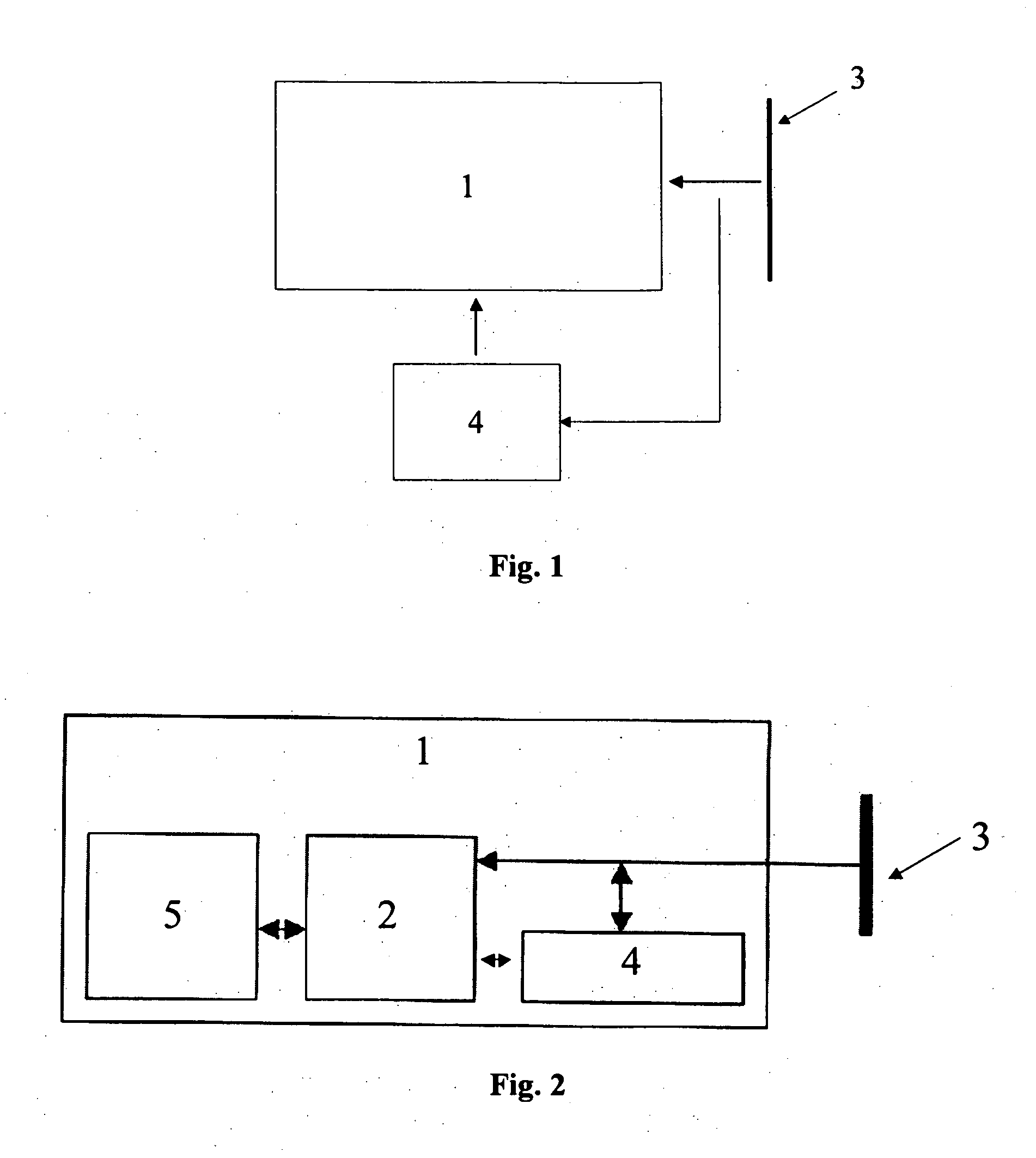
[0035]FIG. 1 shows an exemplary embodiment of the present invention. The electric window dimming device 1 for reducing the light transmission of a window comprises a capacitance 4. The electric window dimming device 1 is connected to the capacitance 4 and to a primary energy source 3 that provides energy. In case of failure of the primary energy source 3, the capacitance 4 supplies energy for the window dimming device 1. Consequently, the dimming devices can still be operated in an emergency.

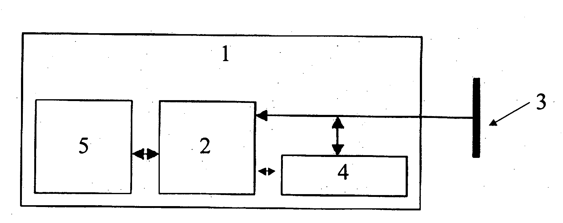
[0036]FIG. 2 shows another exemplary embodiment of the electric window dimming device 1 according to the invention. The electric window dimming device 1 for reducing the light transmission of a window comprises a capacitance 4 and a control unit 2 with a first and a second interface. In this case, the window dimming device 1 is a...


PUM


Abstract

An electric window dimming device for reducing the light transmission of a window for an aircraft. The electric window dimming device comprises a capacitance. The electric window dimming device is adapted for being connected to the capacitance and to a primary energy source that provides energy. If the primary energy source fails, the capacitance supplies energy for electric window dimming device.

Description

CROSS-REFERENCE TO RELATED APPLICATIONS[0001]This application claims the benefit of the filing date of U.S. Provisional Patent Application No. 60 / 763,280 filed Jan. 30, 2006, the disclosure of which is hereby incorporated herein by reference.BACKGROUND OF THE INVENTION[0002]The present invention relates to an electric window dimming device, a window unit, a method for controlling an electric window dimming device, an aircraft as well as the utilization of the electric window dimming device in an aircraft.[0003]Modern window technology may make it possible to equip aircraft windows in today's commercial aircraft with electrically operated window shades. This free adjustability by an electric window shade makes it possible for the passengers to adjust the light transmission of an aircraft window in accordance with personal preferences. Possible dimming devices for windows are, for example, electrically or electromechanically operated awnings or covering devices that may enable the pas...

Claims


Application Information

Patent Timeline
IPC IPC(8): G02B26/02B64C1/14
CPCB60J3/04B64D2011/0061B64C1/1476
Inventor STAVAEUS, MIKAELWISCH, BODOSUESS, WOLFGANGROWOLD, LARS
Owner AIRBUS OPERATIONS GMBH
Learn More