

Partitioned heatsink for improved cooling of an LED bulb
a heatsink and led bulb technology, applied in semiconductor devices, light sources, lighting and heating apparatus, etc., can solve the problems of % of power loss, inefficient incandescent bulbs, and each suffers from certain drawbacks
- Summary
- Abstract
- Description
- Claims
- Application Information
AI Technical Summary
Benefits of technology
Problems solved by technology
Method used
Image

Examples
Embodiment Construction
[0018]The following description is presented to enable a person of ordinary skill in the art to make and use the various embodiments. Descriptions of specific devices, techniques, and applications are provided only as examples. Various modifications to the examples described herein will be readily apparent to those of ordinary skill in the art, and the general principles defined herein may be applied to other examples and applications without departing from the spirit and scope of the various embodiments. Thus, the various embodiments are not intended to be limited to the examples described herein and shown, but are to be accorded the scope consistent with the claims.
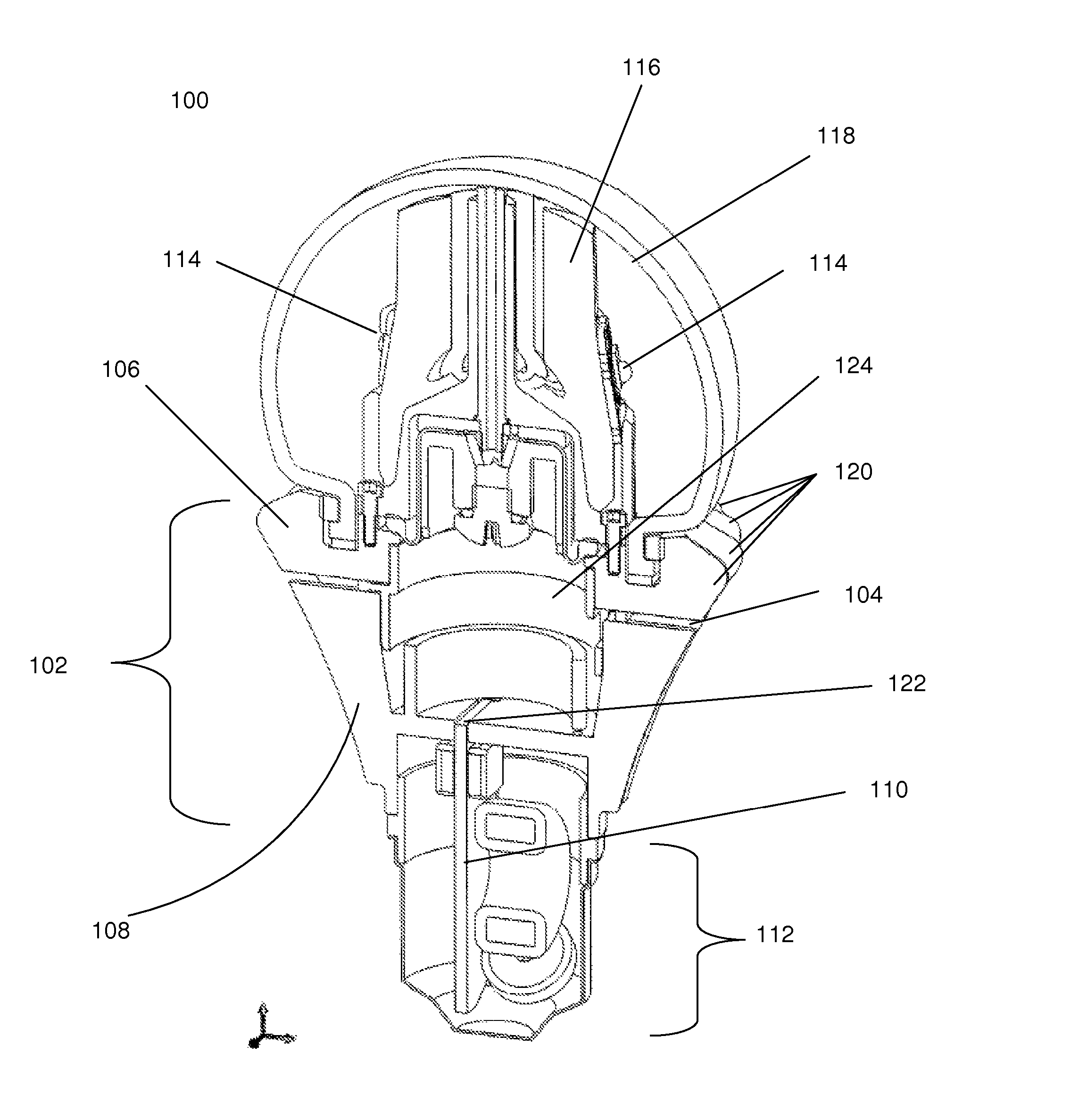
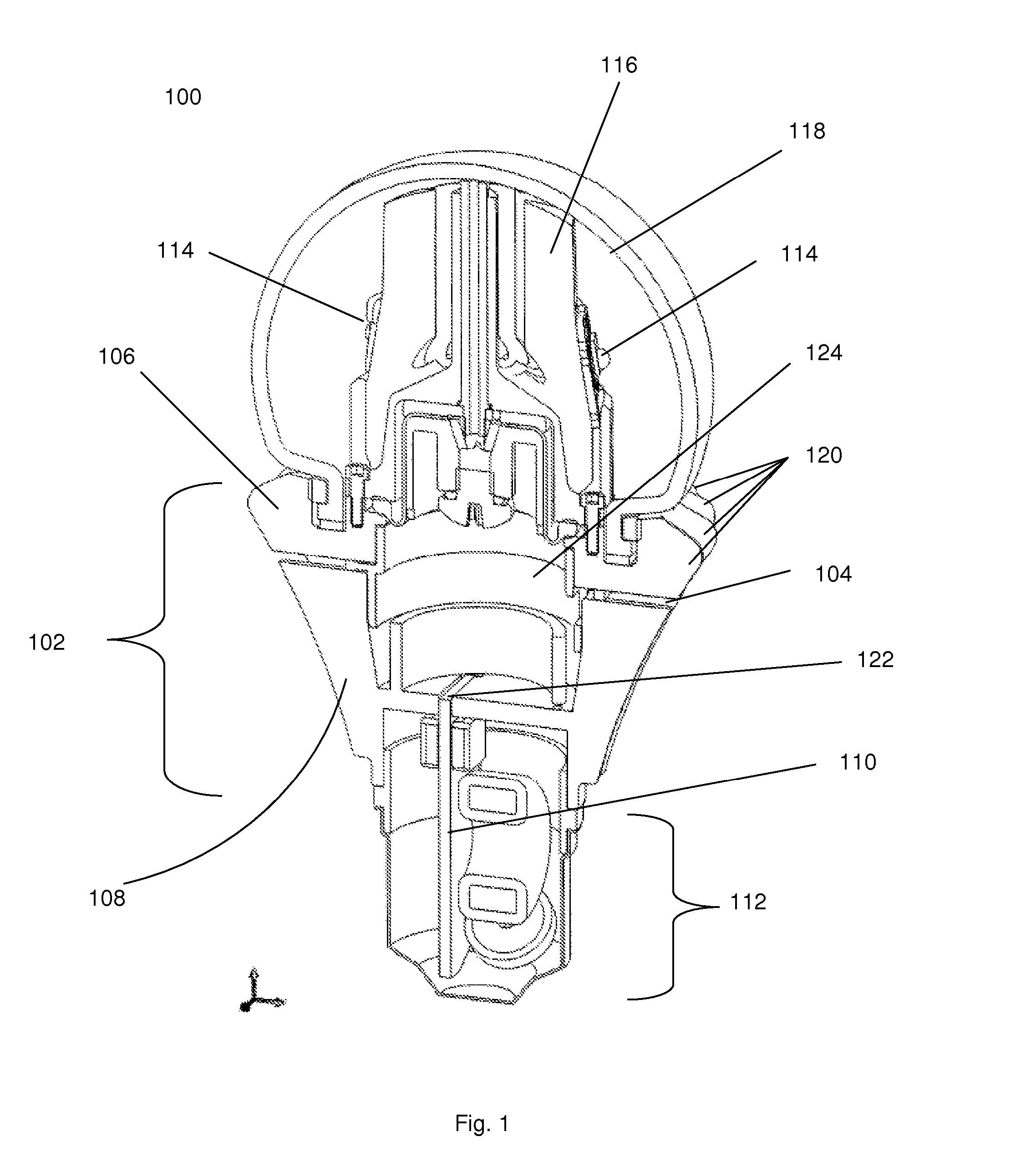
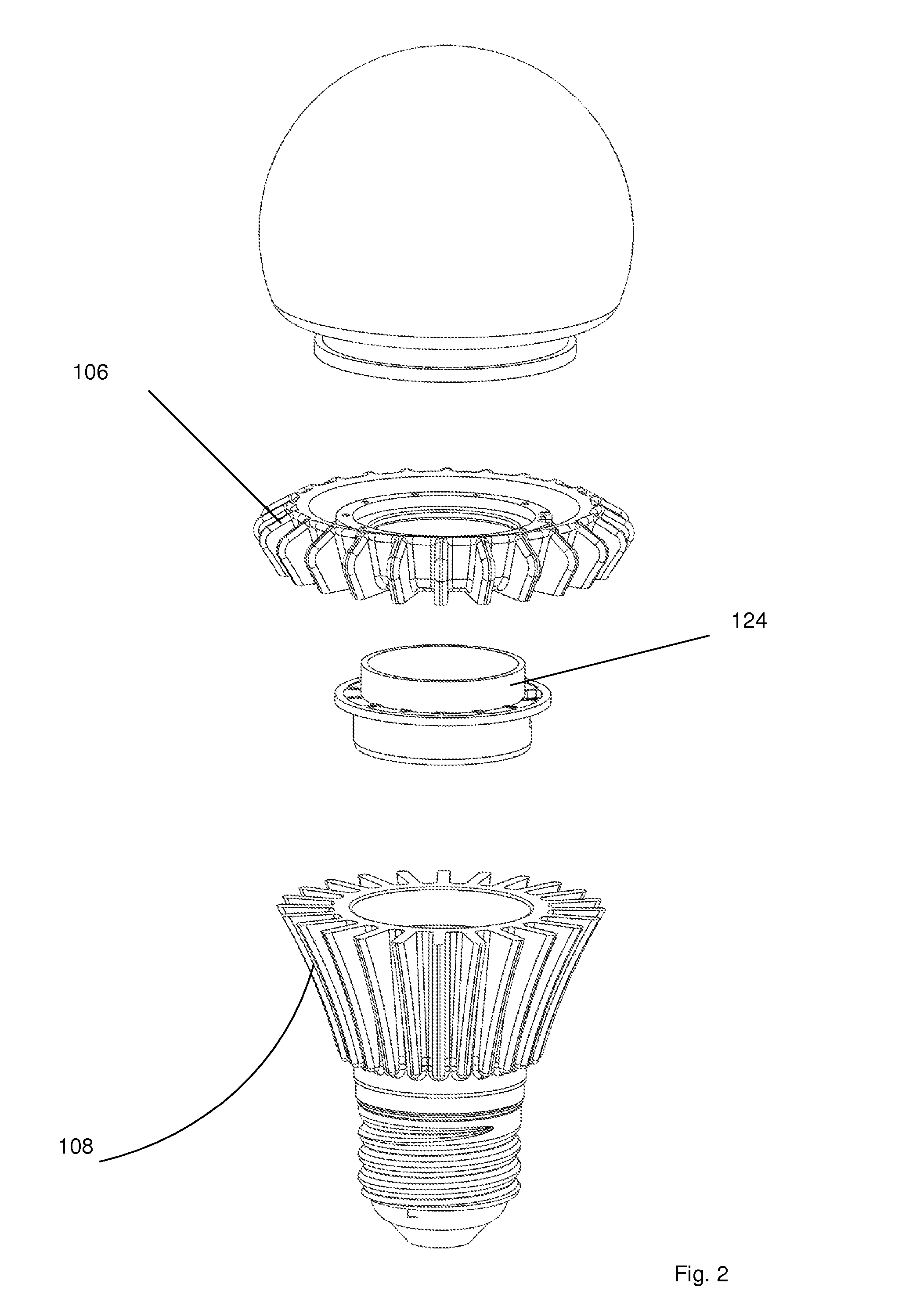
[0019]FIG. 1 depicts an exemplary embodiment of LED bulb 100 using partitioned heatsink 102 for improved cooling. Thermal break 104 partitions heatsink 102 into upper heatsink partition 106 and lower heatsink partition 108. The amount of heat that may be dissipated by each partition depends, in part, on the amount of su...
PUM
 Abstract
Description
Claims
Application Information