Medical robotic system and method of controlling the same

a robotic system and robotic system technology, applied in the field of medical robotic systems and a method of controlling the same, can solve the problems of reducing affecting the accuracy of positioning, so as to prevent the deterioration of positioning accuracy and improve the time delay characteristics

Active Publication Date: 2014-06-03
LG ELECTRONICS INC
View PDF12 Cites 170 Cited by
  • Summary
  • Abstract
  • Description
  • Claims
  • Application Information

AI Technical Summary

Benefits of technology

[0020]Thus, it is an object of the present invention to provide a medical robotic system and control method for precisely measuring the force during the minimally invasive surgery.
[0021]It is also an object of the present invention to provide a medical robotic system and control method for improving the time delay characteristics.
[0022]It is also an object of the present invention to provide a medical robotic system and control method for preventing deterioration of positioning accuracy.
[0043]The present invention provides a medical robotic system and control method which can precisely measure the force during the minimally invasive surgery and reflect the measured fore to a surgeon's hand such that the surgeon is able to perform a more intuitive surgery.
[0044]The present invention also provides a medical robotic system and control method which improve the time delay characteristics by detecting a contact.
[0045]The present invention also provides a medical robotic system and control method which can prevent deterioration of positioning accuracy because the system does not require any additional sensors or the like.

Problems solved by technology

However, there are also many disadvantages of current minimally invasive surgical technology.
However, by inserting an instrument through a small aperture, such as one made in a patient to effectuate a minimally invasive procedure, two degrees of freedom are lost.
It is this loss of freedom of movement within the surgical site that has substantially limited the types of minimally invasive surgery procedures that are performed.
Manipulating such instruments can be awkward.
It has been found that a high level of dexterity is required to accurately control the instruments.
The tremor further increases the difficulty of performing minimally invasive cardiac procedures.
The length and construction of instruments reduces the surgeon's ability to feel force exerted by tissues and organs on the end effector of the tool.
However, proposed methods of performing telesurgery create many new challenges.
One of the challenges is transmitting force from the surgical instrument back to the surgeon's hands such that the surgeon can feel resistance to movements of the instruments when the instrument contacts tissue.
The system is currently adapted to a few of the surgical robots however it is not widely used because of problems such as time delay.
However, these methods have the following disadvantages.
First, the method using torque sensors attached to actuators can induce additional position errors due to the means of measuring torque.
Second, in the method using sensor attached to end effectors, it is necessary to induce a transformation of a link portion so as to increase sensitivity of the sensor, and this may deteriorate the position accuracy.
The method also induces additional expenses for the surgical instruments.
Third, the method using a sensor attached to a trocar needle may induce malfunction when the trocar needle is detached from the incision during the surgical procedure.
Forth, the method using a sensor attached to ends of the instrument may induce problems in the expenses, sterilization and shielding EMI.
Moreover, when a control action is inputted using a small mobile terminal, a user may have difficulty in inputting the corresponding control action.

Method used


Image

  • Medical robotic system and method of controlling the same
  • Medical robotic system and method of controlling the same
  • Medical robotic system and method of controlling the same

Examples


Embodiment Construction

[0057]Reference will now be made in detail to the preferred embodiments of the present invention, examples of which are illustrated in the accompanying drawings.

[0058]Exemplary embodiments described hereinafter are combinations of elements and features of the present invention. The elements or features may be considered selective unless otherwise mentioned. Each element or feature may be practiced without being combined with other elements or features. Further, an embodiment of the present invention may be constructed by combining parts of the elements and / or features. Operation orders described in embodiments of the present invention may be rearranged. Some constructions of any one embodiment may be included in another embodiment and may be replaced with corresponding constructions of another embodiment.

[0059]To simplify the description herein and in the claims, the term “joint” is to be understood as a connection (translational or revolute) between two links, and may include gears...


PUM


Abstract

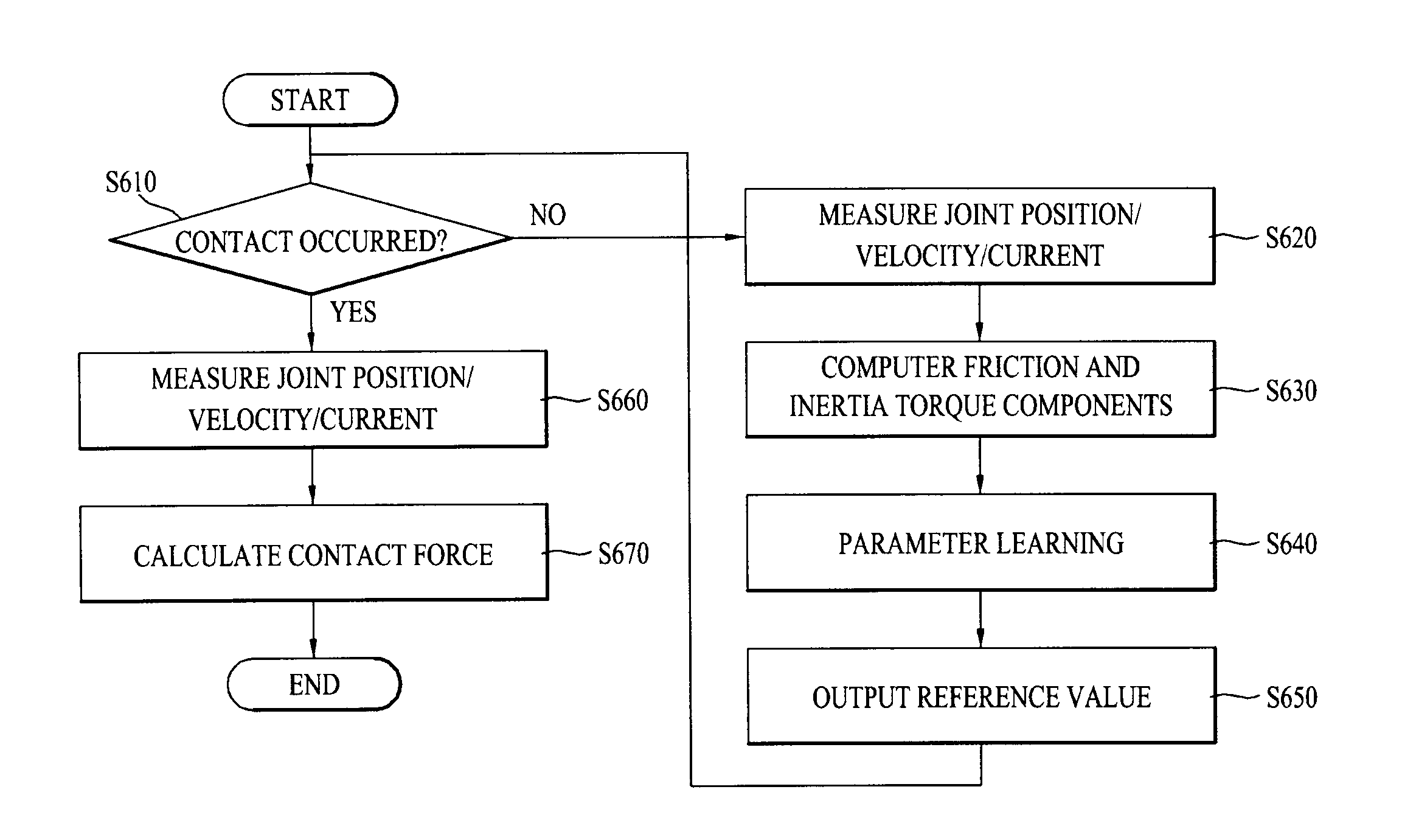
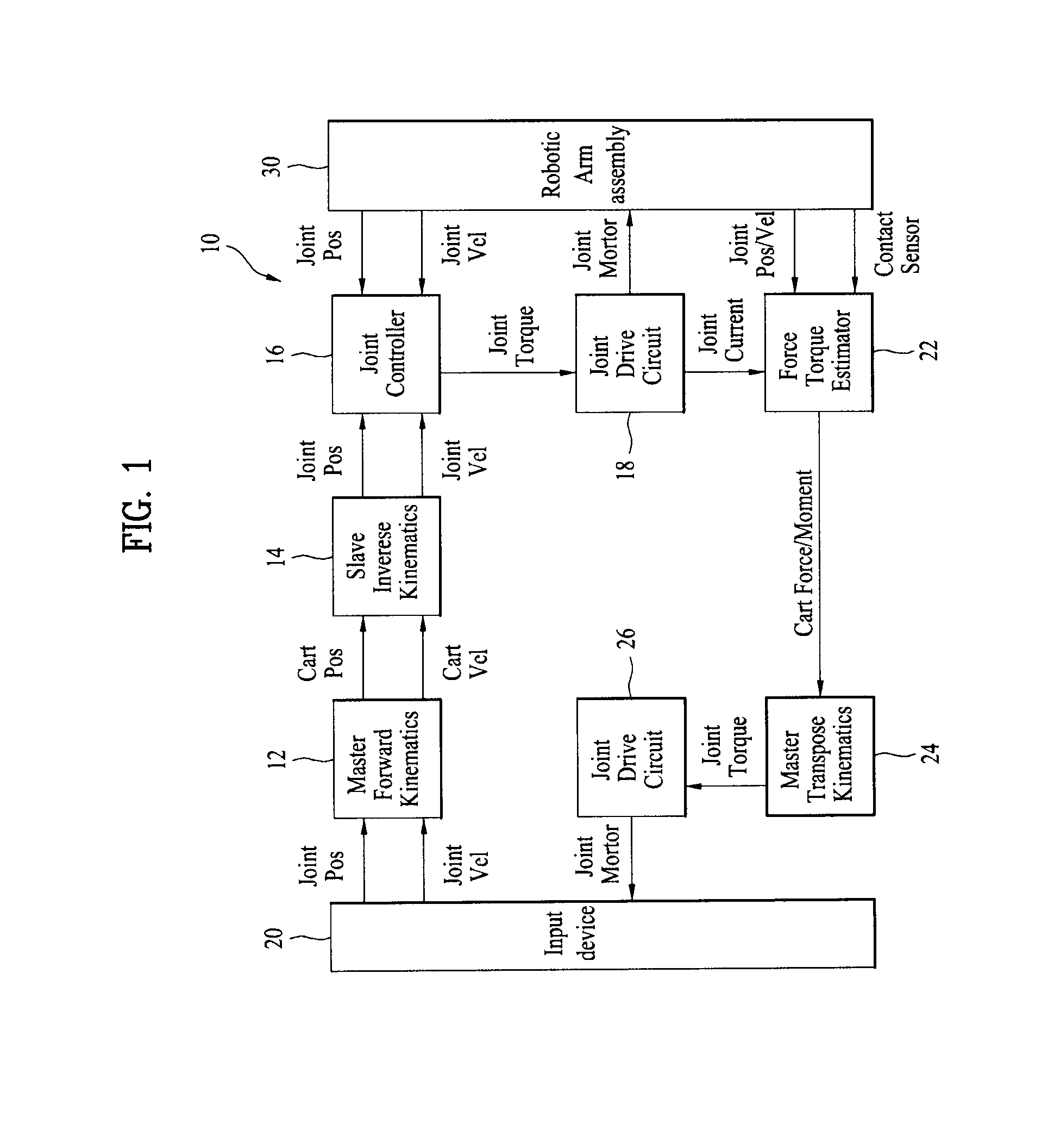
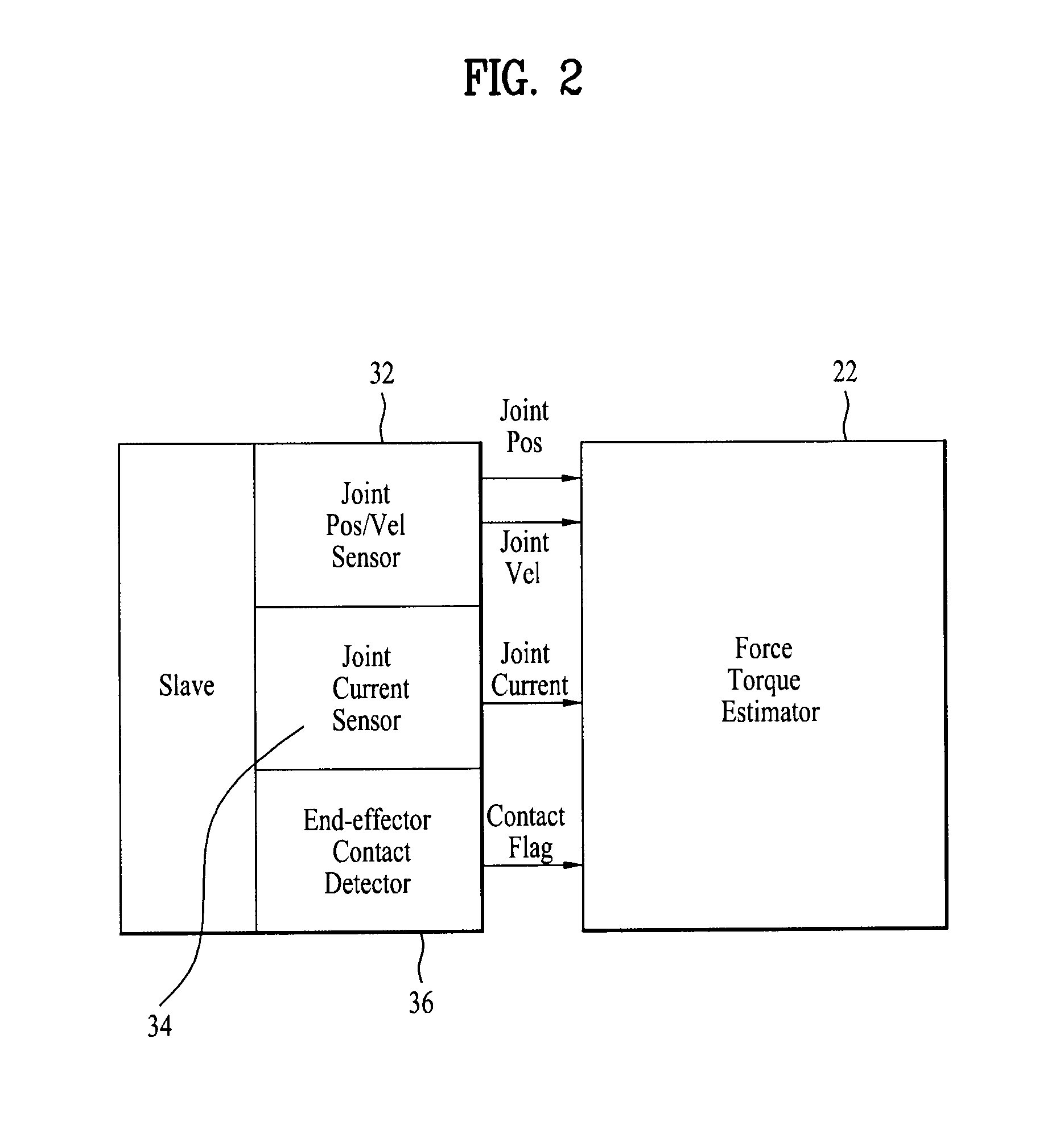
A medical robotic system and method for controlling the system are provided to precisely measure contact force during the minimally invasive surgery. In one embodiment, a medical robotic system includes an input device, a robotic arm assembly, a surgical instrument operably coupled to the robotic arm assembly, the surgical instrument including a contact detection unit configured to detect a contact of the surgical instrument with tissue of a patient, a current measurement unit configured to measure a joint current in the robotic arm assembly, a position / velocity measurement unit configured to measure a joint position and a joint velocity in the robotic arm assembly, an external force calculation unit configured to calculate size and direction of a contact force caused by the contact of the surgical instrument to the tissue based on the joint currents, positions and velocities measured when the contact is occurred and measured when the contact is not occurred.

Description

BACKGROUND OF THE INVENTION[0001]1. Field of the Invention[0002]The present invention relates a medical robotic system and a method of controlling medical robotic system and in particular, relates to a force-reflecting medical robotic system and a method of controlling the system.[0003]2. Discussion of the Related Art[0004]Minimally invasive surgery can reduce the amount of extraneous tissue which must be damaged during diagnostic or surgical procedures in comparison with a conventional open surgery, thereby reducing patient recovery time, discomfort, and deleterious side effects. In addition, the minimally invasive manner can minimize the trauma due to surgical procedures. Thus, the number of surgical procedures using the minimally invasive manner is gradually increasing in various medical fields such as general surgery, urology, gynecology, and cardio surgery.[0005]However, there are also many disadvantages of current minimally invasive surgical technology. In essence, during conv...

Claims


Application Information

Patent Timeline
Patent Type & Authority Patents(United States)
IPC IPC(8): A61B19/00
CPCA61B2019/502A61B2019/465A61B2019/2223A61B19/2203A61B2019/2292A61B34/30A61B34/37A61B34/76A61B2034/102A61B2090/065
Inventor JUN, HONGGULCHANG, YOONYOUNGPAIK, WOOHYUN
Owner LG ELECTRONICS INC
Why Eureka
Try Eureka