Battery pack having waterproof structure

a battery pack and waterproof technology, applied in the field of batteries, can solve the problems of short circuit between the terminals of the rechargeable battery or the electronic circuit, water may enter the battery pack casing, and it is not easy to provide a completely waterproof structure in the battery pack, so as to effectively prevent unintended electric conduction, easy to drain out the battery pack, and effective prevent water from entering the rechargeable battery

Active Publication Date: 2014-06-03
PANASONIC ENERGY CO LTD +1
View PDF11 Cites 21 Cited by
  • Summary
  • Abstract
  • Description
  • Claims
  • Application Information

AI Technical Summary

Benefits of technology

[0012]Also, a battery pack according to a third aspect of the present invention can be attached to a charger 100, and includes a plurality of rechargeable batteries 39, a battery holder 70, a pack circuit board 74, a casing 31, external connection terminals 33 and a lock hook 37b. The charger 100 can charge the rechargeable batteries of the battery pack. The battery holder 70 holds the rechargeable batteries 39. The pack circuit board 74 includes an electronic circuit connected to the rechargeable batteries 39. The casing 31 accommodates the battery holder 70 and the pack circuit board 74. The external connection terminals 33 are fastened onto the pack circuit board 74 and are connected to the rechargeable batteries 39. The external connection terminals are exposed externally of the casing 31. The lock hook 37b protrudes from a surface of the casing 31, and holds the battery pack with the battery pack being attached to the charger 100. A hook opening window 24 is opened in one of the surfaces of the casing so that the lock hook 37b can protrude from the surface of the casing 31. A drain hole 28 is opened in another surface of the casing other than the one of the surfaces on which the hook opening window 24 is opened. A partition rib 25 is arranged between a path and the electronic circuit so that the path is separated from the electronic circuit. The path extends inside the casing 31 from the hook opening window 24 and communicates with the hook opening window 24. The electronic circuit is mounted in the pack circuit board 74. The hook opening window 24 communicates with the drain hole 28 through the communication path, which is formed by the partition rib 25. According to this construction, even if water enters the battery pack through the hook opening window, the partition rib can prevent the water from flowing toward the electronic circuit, which is mounted on the pack circuit board. In addition, the water is guided to the drain hole after entering the battery pack. Therefore, it is possible to effectively prevent unintended electric conduction.
[0013]In addition, in a battery pack according to a fourth aspect of the present invention, the communication path can be formed at least partially on the upper surface of the battery holder 70. According to this construction, since the communication path can be formed on the back surface of the battery holder, which accommodates the rechargeable batteries, it is possible to effectively prevent ingress of water onto the rechargeable batteries.
[0014]In addition, in a battery pack according to a fifth aspect of the present invention, the upper surface of the battery holder 70 is inclined at a downward angle toward the drain hole 28. According to this construction, since, even if water enters the battery pack through the hook opening window, the water can be guided to the drain hole by the inclined upper surface along the communication path, and the water can be easily drained out of the battery pack.
[0015]In addition, in a battery pack according to a sixth aspect of the present invention, the edges of the partition rib 25 can partially contact the surface of the external connection terminal 33. The external connection terminal 33 can have a soldering part that is arranged for wiring in proximity to the contact part of the external connection terminal with the partition rib 25. A protruding stopper portion 88 can be formed in this soldering part. According to this construction, the protruding stopper portion can limit spreading of solder in a soldering operation. As a result, it is possible to avoid the solder from spreading to the contact part. For this reason, it is possible to avoid the bulge of spreading solder from preventing contact between the partition rib and the pack circuit board in the contact part. Thus, the partition rib can surely contact the pack circuit board. Therefore, it is possible to effectively prevent water from entering the battery pack.
[0016]In addition, in a battery pack according to a seventh aspect of the present invention, the protruding stopper portion 88 can be formed on the surface of the external connection terminal 33 by drawing. According to this construction, the protruding stopper portion can be easily formed integrally with the surface of the external connection terminal.
[0017]In addition, in a battery pack according to an eighth aspect of the present invention, a holding rib portion 27 can be arranged inside the casing 31. The holding rib portion 27 guides the upper end of the external connection terminal 33, and holds the upper end of the external connection terminal 33 from both sides of the external connection terminal 33. According to this construction, the external connection terminal can be stably held. Therefore, it is possible to improve the reliability of the battery pack.

Problems solved by technology

On the other hand, if water comes into the battery pack, the terminals of the rechargeable battery or the electronic circuit may be short-circuited.
However, since the battery pack has the movable part in the lock structure, it is not easy to provide a completely waterproof structure in the battery pack.
For this reason, there is a problem that water may come into the casing of the battery pack through this opening.
In addition, if water enters the battery pack, it is not easy to drain the water from the battery pack.
The water may move to the rechargeable battery or the electronic circuit board, and may cause unintended electric conduction.
There is also a problem that water may come into the case through this opening.

Method used


Image

  • Battery pack having waterproof structure
  • Battery pack having waterproof structure
  • Battery pack having waterproof structure

Examples


Embodiment Construction

)

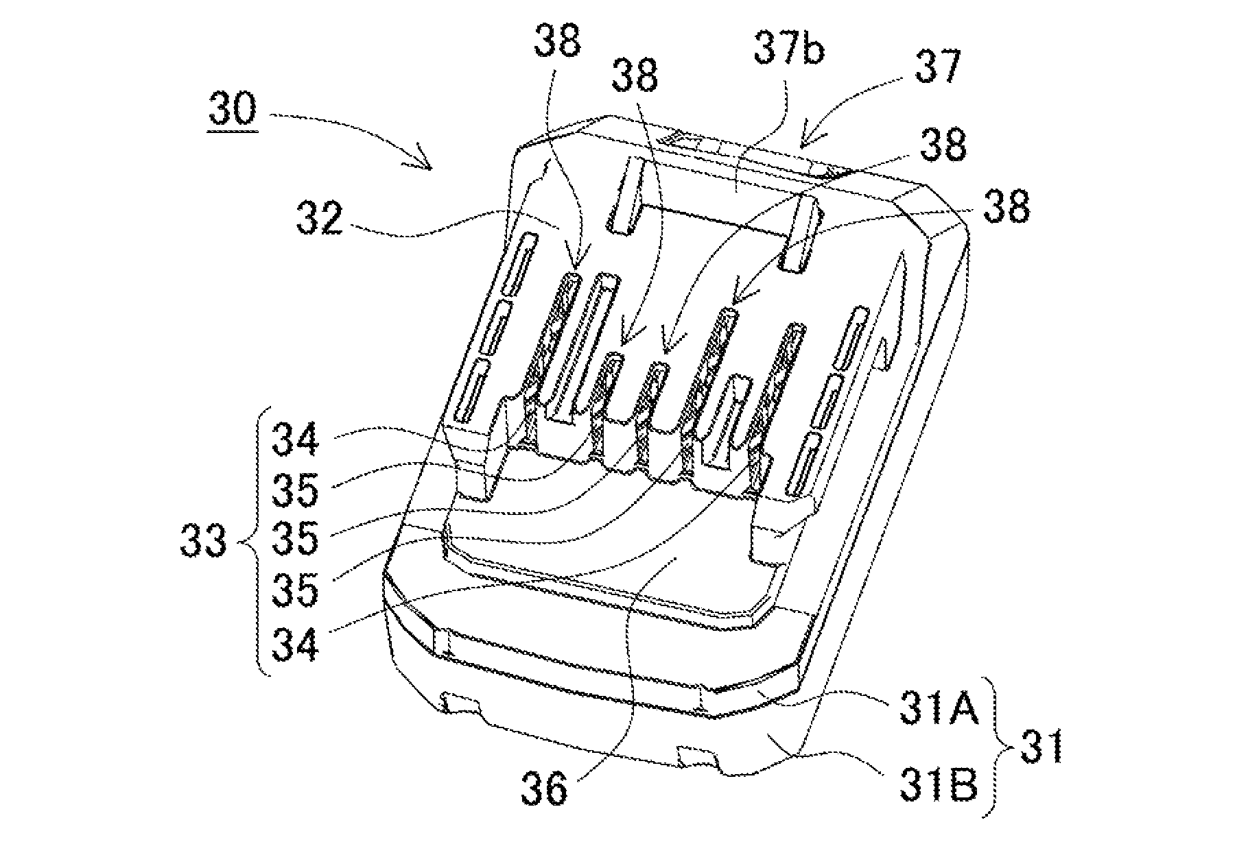
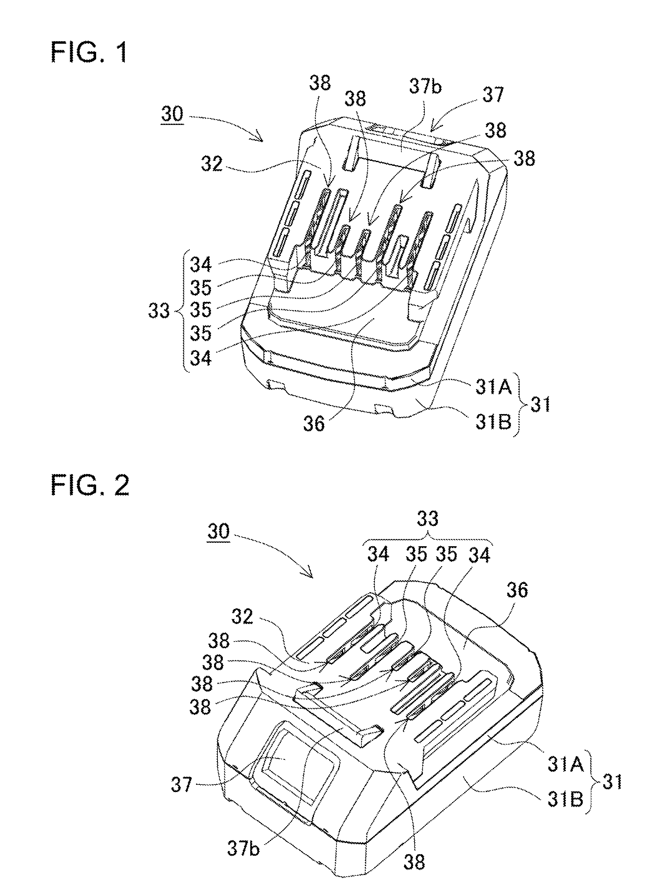
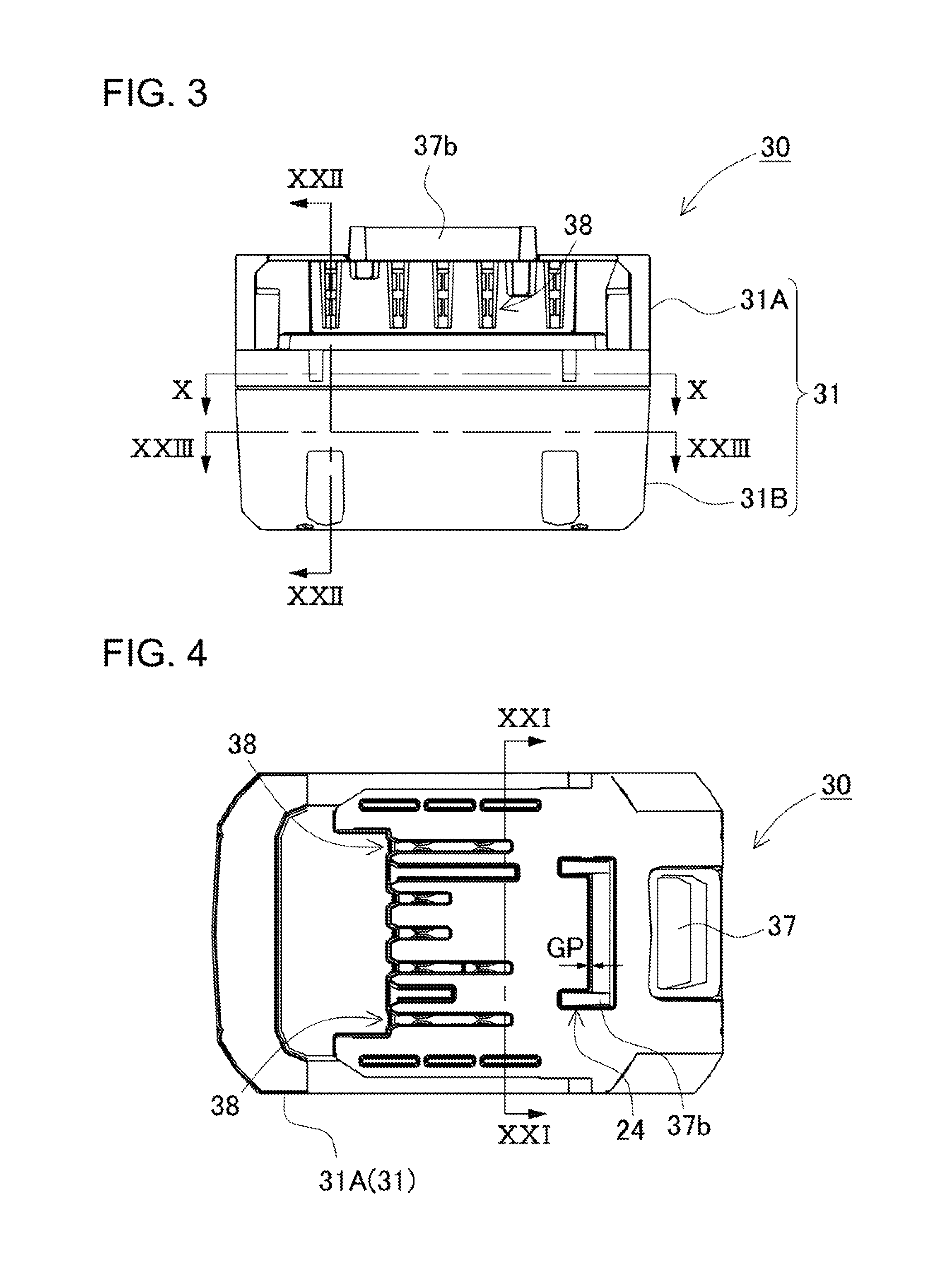
[0050]The following description will describe embodiments according to the present invention with reference to the drawings. It should be appreciated, however, that the embodiments described below are illustrations of a battery pack used therein to give a concrete form to technical ideas of the invention, and a battery pack of the invention is not specifically limited to description below. Furthermore, it should be appreciated that the members shown in the claims attached hereto are not specifically limited to members shown in the embodiments. Unless otherwise specified, any dimensions, materials, shapes and relative arrangements of the members described in the embodiments are given as an example and not as a limitation. Additionally, the sizes and the positional relationships of the members in each of the drawings are occasionally shown larger exaggeratingly for ease of explanation. Members that are the same as or similar to those of this invention are denoted with the same design...


PUM

PropertyMeasurementUnit
output voltageaaaaaaaaaa
electric poweraaaaaaaaaa

Abstract

A battery pack includes terminals (33) and a lock hook (37b). The terminals (33) are fastened onto a circuit board (74) and connected to rechargeable batteries (39). The terminals are exposed externally of a casing (31). The hook (37b) protrudes from a surface of the casing (31), and holds the battery pack on a charger (100). A hook opening window (24) is open in one of the surfaces of the casing. The hook (37b) can protrude from the surface of the casing (31). A drain hole (28) is open in another surface of the casing. A partition rib (25) is arranged between a path and an electronic circuit. The path is separated from the circuit. The path extends inside the casing (31) from the window (24). The circuit is mounted on the board (74). The window (24) communicates with the hole (28) through the path.

Description

BACKGROUND OF THE INVENTION[0001]1. Field of the Invention[0002]The present invention relates to a battery pack which is detachably attached to electric equipment such as an electric tool and supplies electric power to the electric equipment.[0003]2. Description of the Related Art[0004]Electric equipment such as an electric tool includes a battery pack which includes a rechargeable battery and is detachably attached to the main unit of the electric equipment. Such electric equipment is useful as a cordless-type tool in construction sites and the like. Since the battery pack can be detached from the main unit of the electric equipment, the detached battery pack can be attached to a charger so that the battery pack is charged. Thus, the battery pack can be repeatedly used. A charger for charging this type of battery pack has been in practical use and includes an attachment portion that is arranged on the upper surface of the charger case and detachably holds the battery pack. Charging...

Claims


Application Information

Patent Timeline
Patent Type & Authority Patents(United States)
IPC IPC(8): H01M2/10H01M10/42H01M2/30H04M1/02H01M2/36H01M50/213H01M50/227H01M50/296H01M50/548H01M50/559
CPCH01M2/1044H01M2/1022H01M2/1055H04M1/0252H01M2/36H01M10/42Y02E60/12H01M2/30Y02E60/10H01M50/213H01M50/227H01M50/548H01M50/296H01M50/559H01M50/216
Inventor YONEDA, HARUHIKOHAINO, MASAMIOGURA, HIRONORIYAMADA, TORU
Owner PANASONIC ENERGY CO LTD
Why Eureka
Try Eureka