
Display panel, manufacturing method thereof and display device

A display panel and substrate technology, which is applied in semiconductor/solid-state device manufacturing, semiconductor devices, electrical components, etc., can solve the problems of difficult process, large film thickness, large depth, etc., and reduce the number of film layers and leakage current Small, depth-reducing effect

Active Publication Date: 2020-09-25
XIAMEN TIANMA MICRO ELECTRONICS
View PDF6 Cites 6 Cited by
  • Summary
  • Abstract
  • Description
  • Claims
  • Application Information

AI Technical Summary

Problems solved by technology

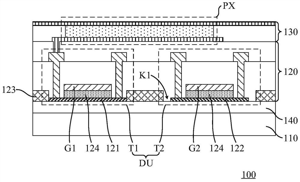
[0004] However, in the prior art when manufacturing an array substrate including both silicon transistors and oxide transistors, it is usually to add a film layer for making oxide transistors on the basis of the original silicon transistors, so that the overall film layer thicker
When the via hole connected to the active layer of the silicon transistor is formed from the surface of the interlayer dielectric layer, the depth of the via hole is relatively large, which makes the process more difficult

Method used


Image

  • Display panel, manufacturing method thereof and display device
  • Display panel, manufacturing method thereof and display device
  • Display panel, manufacturing method thereof and display device

Examples


Embodiment Construction

[0020] The characteristics and exemplary embodiments of various aspects of the present invention will be described in detail below. In order to make the purpose, technical solutions and advantages of the present invention clearer, the present invention will be further described in detail below in conjunction with the accompanying drawings and specific embodiments. It should be understood that the specific embodiments described here are only configured to explain the present invention, not to limit the present invention. It will be apparent to one skilled in the art that the present invention may be practiced without some of these specific details. The following description of the embodiments is only to provide a better understanding of the present invention by showing examples of the present invention.

[0021] It should be noted that in this article, relational terms such as first and second are only used to distinguish one entity or operation from another entity or operation...


PUM

PropertyMeasurementUnit
depthaaaaaaaaaa

Abstract

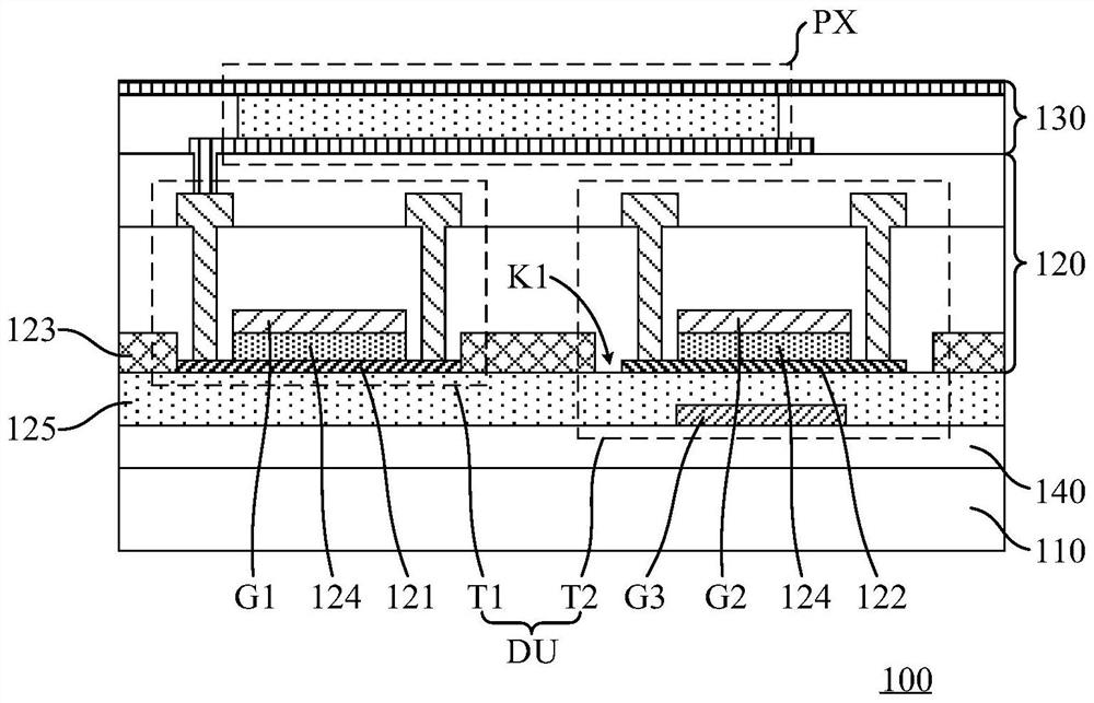
The invention discloses a display panel, a manufacturing method thereof and a display device. The display panel includes a substrate and a driving array layer; the driving array layer comprises a silicon transistor and an oxide transistor; the silicon transistor comprises a silicon active layer and a first grid electrode; the oxide transistor comprises an oxide active layer and a second grid electrode; the silicon active layer and the oxide active layer are arranged on the same layer; the driving array layer further comprises a silicon nitride gate insulating layer and a first silicon oxide gate insulating layer; at least one of the silicon nitride gate insulating layer and the first silicon oxide gate insulating layer is positioned on the surface, far away from the substrate, of the silicon active layer; the silicon nitride gate insulating layer comprises a first opening; the orthographic projection of the first opening on the substrate covers the orthographic projection of the oxideactive layer on the substrate; and the first silicon oxide gate insulating layer is further located on the surface, away from the substrate, of the oxide active layer. According to the display panel provided by the embodiment of the invention, the manufacturing difficulty of the display panel comprising two kinds of semiconductor material transistors is reduced.

Description

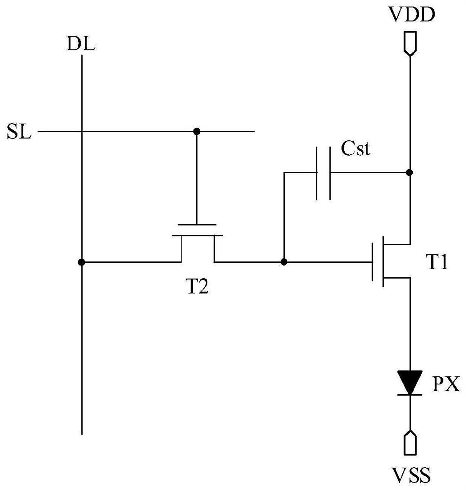
technical field [0001] The present invention relates to the display field, in particular to a display panel, a manufacturing method thereof, and a display device. Background technique [0002] Organic Light Emitting Display (OLED) display devices, as flat display devices, are widely used in mobile phones, televisions, and personal digital assistants due to their advantages of high image quality, power saving, thin body, and wide application range. , digital cameras, notebook computers, desktop computers and other consumer electronics products have become the mainstream of display devices. [0003] OLED display devices generally adopt an active matrix (AM) driving method, that is, an array substrate of an OLED display device includes a plurality of pixel driving units arranged in an array, and each pixel driving unit is used to drive a corresponding light-emitting element to emit light. Wherein, each pixel driving unit includes at least two transistors. For example, each pi...

Claims


Application Information

Patent Timeline
Patent Type & Authority Applications(China)
IPC IPC(8): H01L27/12H01L21/77H01L27/32
CPCH01L27/1229H01L27/1248H01L27/127H10K59/1213
Inventor 谢锋
Owner XIAMEN TIANMA MICRO ELECTRONICS
Learn More