
Fixing device having a plurality of heat sources and a plurality of temperature detectors and image forming apparatus including same

a technology of fixing device and temperature detector, which is applied in the direction of electrographic process apparatus, instruments, optics, etc., can solve the problems of shortening the warm-up time of the fixing device, affecting the durability of the fixing belt, and affecting the stability of the temperature of the fixing bel

Inactive Publication Date: 2014-06-03
RICOH KK
View PDF128 Cites 2 Cited by
  • Summary
  • Abstract
  • Description
  • Claims
  • Application Information

AI Technical Summary

Benefits of technology

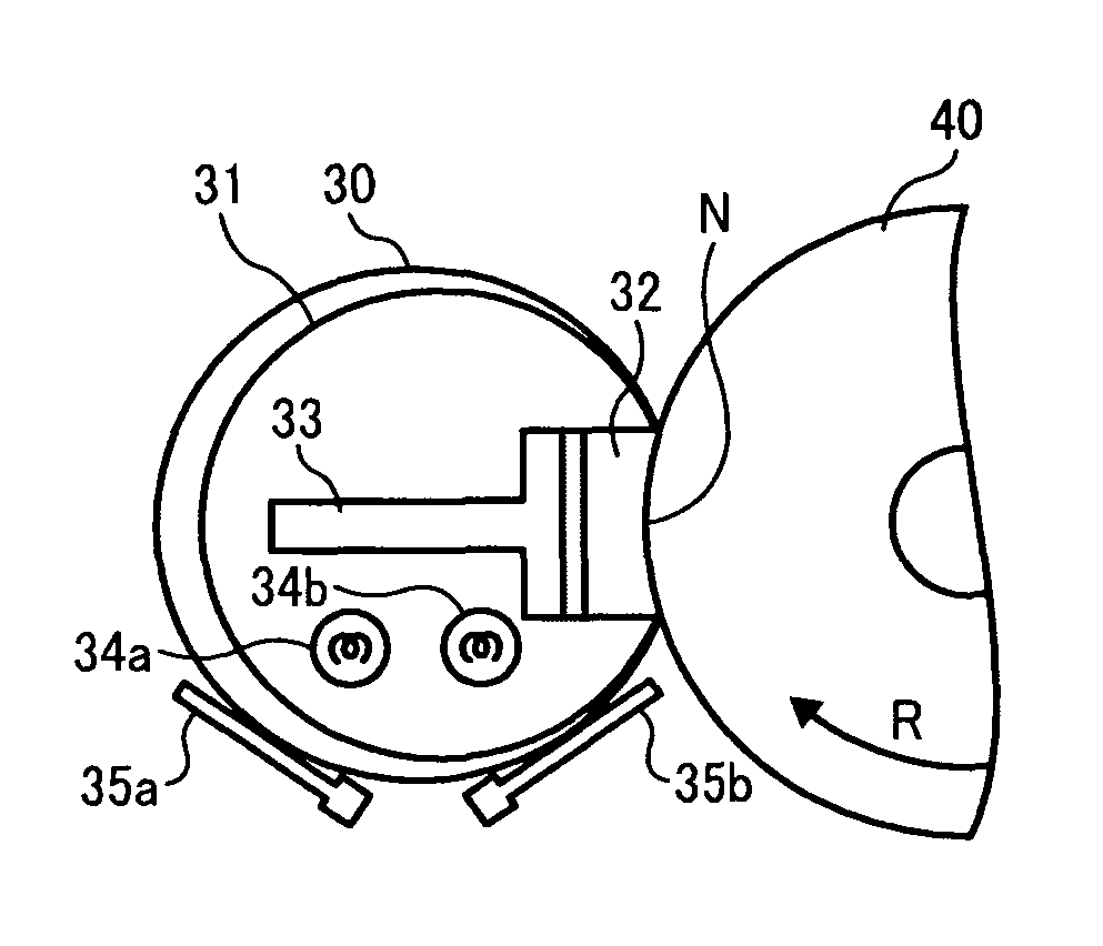
[0090]In the fixing device, the temperature detectors are disposed at positions suitable in response and / or sensitivity so that the temperature detectors are most sensitive and heat-intensive for the corresponding halogen heaters, and the temperature detection of the temperature detectors is not affected by the clearance between the fixing belt and the heat conductive member. Such a configuration can promptly and accurately detect a change in the temperature of the heating member caused by, for example, sheet passing through the nip, and accurately and stably control the temperature of the fixing nip N.

Problems solved by technology

However, a film-heating type fixing device like that described in JP-H04-044075-A has limitations in durability of a fixing belt and stability of the temperature of the fixing belt.
Such a configuration can shorten the warm-up time of the fixing device.
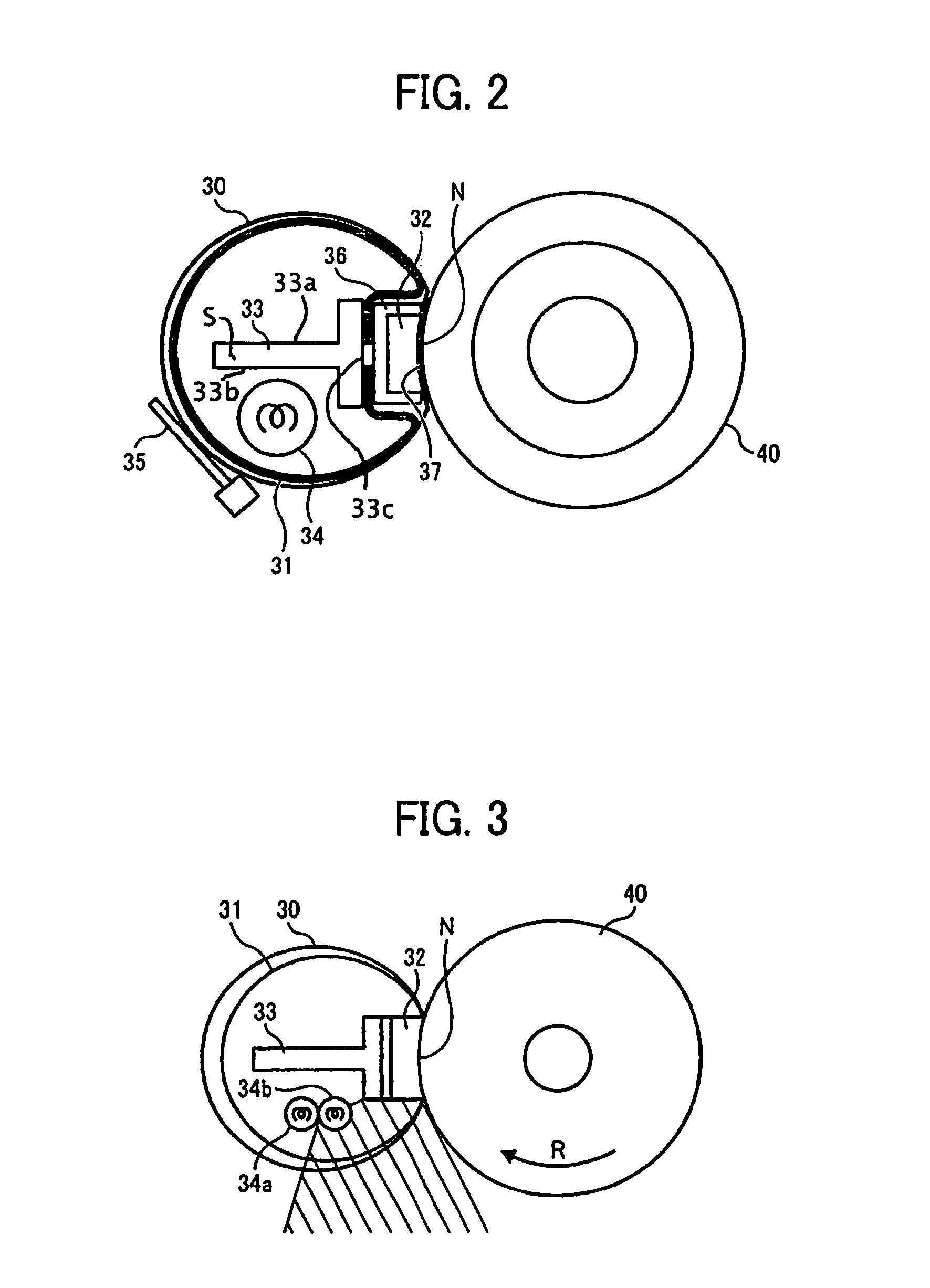
However, for the fixing device, since a plurality of halogen heaters is arranged side by side in contact with each other in the circumferential direction of the fixing belt, there is a dead angle at which a portion of radiation heat emitted from one halogen heater is blocked by the other halogen heater.
In such a dead angle, a portion of the amount of heat from one halogen heater for heating the metal heat-conductive member is absorbed by the other halogen heater, thus preventing optimization of heating efficiency.
Further, detecting the temperature of the fixing belt in such a dead angle by a temperature detector (e.g., thermistor) is disadvantageous in terms of responsiveness and sensitivity.
As a result, although the fixing device can shorten the warm-up time, the fixing belt might be overheated if, for example, continuous activation of the heater occurs due to a failure of the fixing device.

Method used


Image

  • Fixing device having a plurality of heat sources and a plurality of temperature detectors and image forming apparatus including same
  • Fixing device having a plurality of heat sources and a plurality of temperature detectors and image forming apparatus including same
  • Fixing device having a plurality of heat sources and a plurality of temperature detectors and image forming apparatus including same

Examples


Embodiment Construction

[0038]In describing embodiments illustrated in the drawings, specific terminology is employed for the sake of clarity. However, the disclosure of this patent specification is not intended to be limited to the specific terminology so selected and it is to be understood that each specific element includes all technical equivalents that operate in a similar manner and achieve similar results.

[0039]Although the exemplary embodiments are described with technical limitations with reference to the attached drawings, such description is not intended to limit the scope of the invention and all of the components or elements described in the exemplary embodiments of this disclosure are not necessarily indispensable to the present invention.

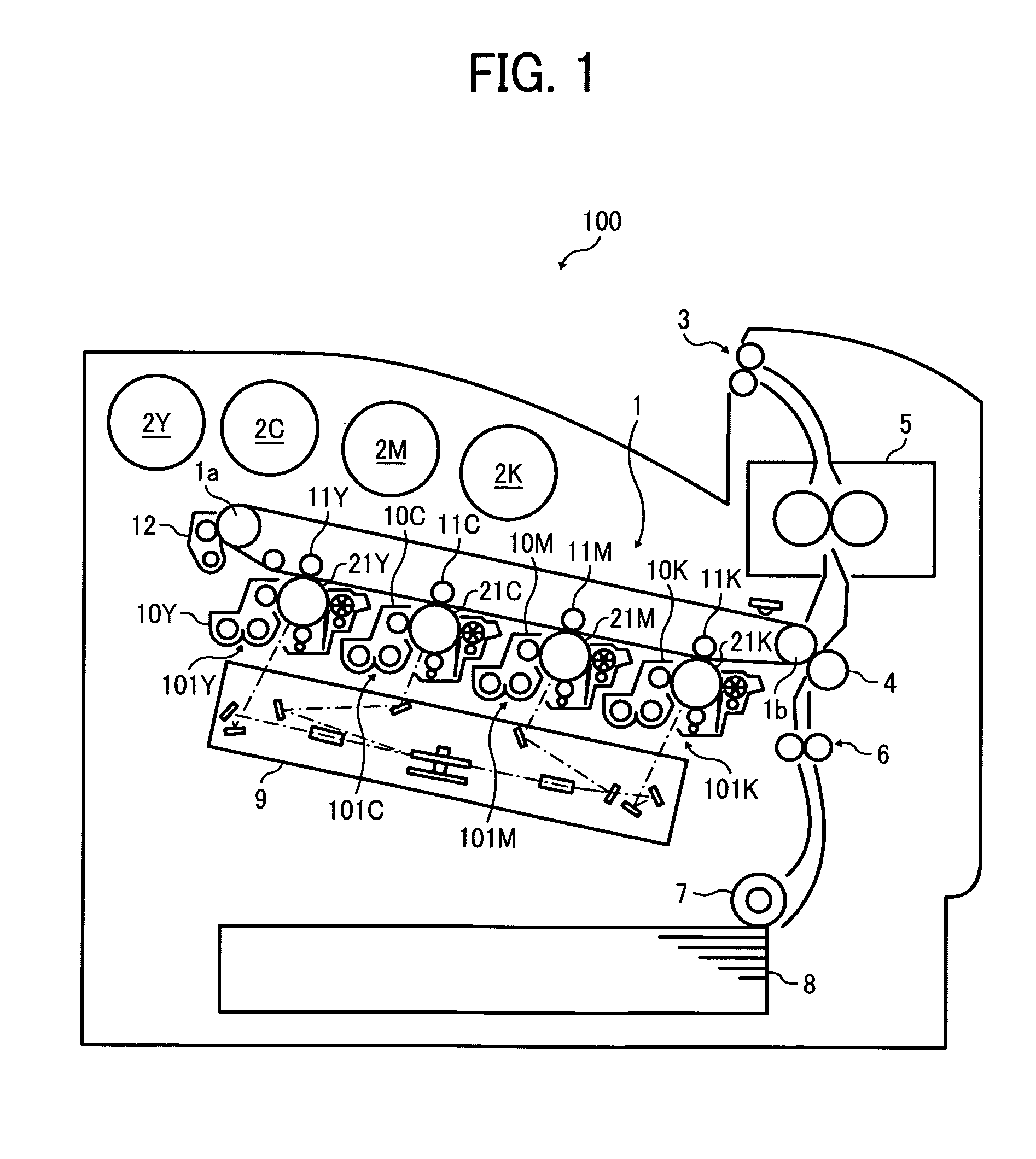
[0040]Referring now to the drawings, wherein like reference numerals designate identical or corresponding parts throughout the several views, exemplary embodiments of the present disclosure are described below with reference to FIGS. 1 to 13.

[0041]FIG. 1 is ...


PUM


Abstract

A fixing device includes a heat conductive member; a flexible fixing belt looped around the heat conductive member, an inner circumference of the flexible fixing belt slidably contacting a portion of an outer circumferential surface of the heat conductive member; a rotary pressing member disposed opposing the heat conductive member; heat sources disposed in a circumferential direction of the fixing belt at a predetermined interval to heat the heat conductive member; and temperature detectors provided to detect a surface temperature of the fixing belt at a detection position at which heating intensity of a corresponding one of the heat sources is not affected by any other one. In operation, the inner circumferential surface of the fixing belt contacts the heat conductive member at a position at which each temperature detector contacts the fixing belt as the detection position or a position proximal to the detection position of each temperature detector.

Description

CROSS-REFERENCE TO RELATED APPLICATIONS[0001]The present patent application claims priority pursuant to 35 U.S.C. §119 from Japanese Patent Application No. 2010-050501, filed on Mar. 8, 2010 in the Japan Patent Office, which is incorporated herein by reference in its entirety.BACKGROUND[0002]1. Field[0003]Exemplary embodiments of the present disclosure relate to a fixing device and an image forming apparatus including the fixing device, and more specifically, a fixing device that fixes an image on a recording medium passing through a nip formed between a heat conductive member and a pressing member via an endless belt, and an image forming apparatus including the fixing device.[0004]2. Description of the Background Art[0005]Related-art image forming apparatuses, such as copiers, facsimile machines, printers, or multifunction apparatuses having at least one of copying, printing, scanning, and facsimile functions, typically form an image on a recording medium according to image data. ...

Claims


Application Information

Patent Timeline
Patent Type & Authority Patents(United States)
IPC IPC(8): G03G15/20
CPCG03G21/20G03G15/20
Inventor YOSHINAGA, HIROSHISHINSHI, AKIRAHASEGAWA, KENICHIYAMASHINA, RYOTAISHIGAYA, YASUNORI
Owner RICOH KK
Learn More