Method of controlling an injection molding machine

a technology of injection molding machine and control method, which is applied in the direction of machines/engines, couplings, fluid couplings, etc., can solve the problems of unfavorable operation control, long time until the desired pressure is achieved, and the residual pressure of the whole circuit from the back-pressure valve to the hydraulic pump cannot be made zero, etc., to achieve high precision and stable operation control

Active Publication Date: 2007-03-08
NISSEI PLASTIC IND CO LTD
View PDF9 Cites 7 Cited by
  • Summary
  • Abstract
  • Description
  • Claims
  • Application Information

AI Technical Summary

Benefits of technology

[0009] The objective of this invention is to provide a method of controlling an injection molding machine which can avoid inconveniences such as the occurrence of shock pressure when switching operations, enable smooth switching, and realize highly precise and stable operation control.
[0010] Also, another objective of this invention is to provide a method of controlling an injection molding machine which can switch operations quickly by lowering the pressure quickly to a specified target pressure even if there is fluidity of the operating oil or flow path resistance of the circuit.

Problems solved by technology

However, the depressurization method (control method) of an injection driving device in the conventional injection molding machine has had the following problems.
First, even if the residual pressure of the injection-side oil chamber of the injection cylinder could be made zero, it is possible that the residual pressure of the whole circuit from the back-pressure valve to the hydraulic pump cannot be made zero (unload pressure).
Therefore, switching from the injection process using the injection cylinder to the measurement process using a measuring motor (an oil motor) for example, the residual pressure of the hydraulic pump side affects the measurement process, which prevents smooth switching by inducing a shock pressure when switching the operations, also preventing an accurate and stable measurement process.
Because it is a depressurization method relying on the natural decrease of pressure, the time until the desired pressure is achieved becomes long due to the fluidity and the operation oil and the flow path resistance of the circuit, and the demand of switching the operational processes quickly cannot be sufficiently met.

Method used


Image

  • Method of controlling an injection molding machine
  • Method of controlling an injection molding machine
  • Method of controlling an injection molding machine

Examples


Embodiment Construction

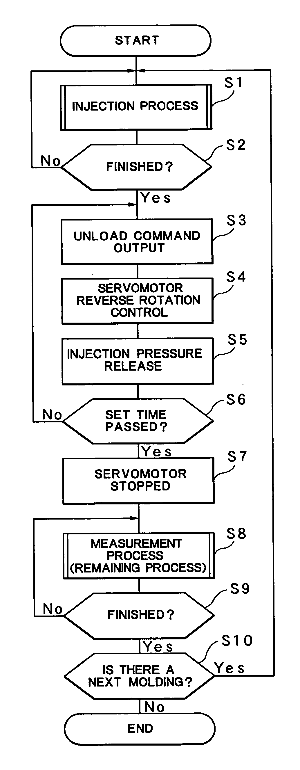
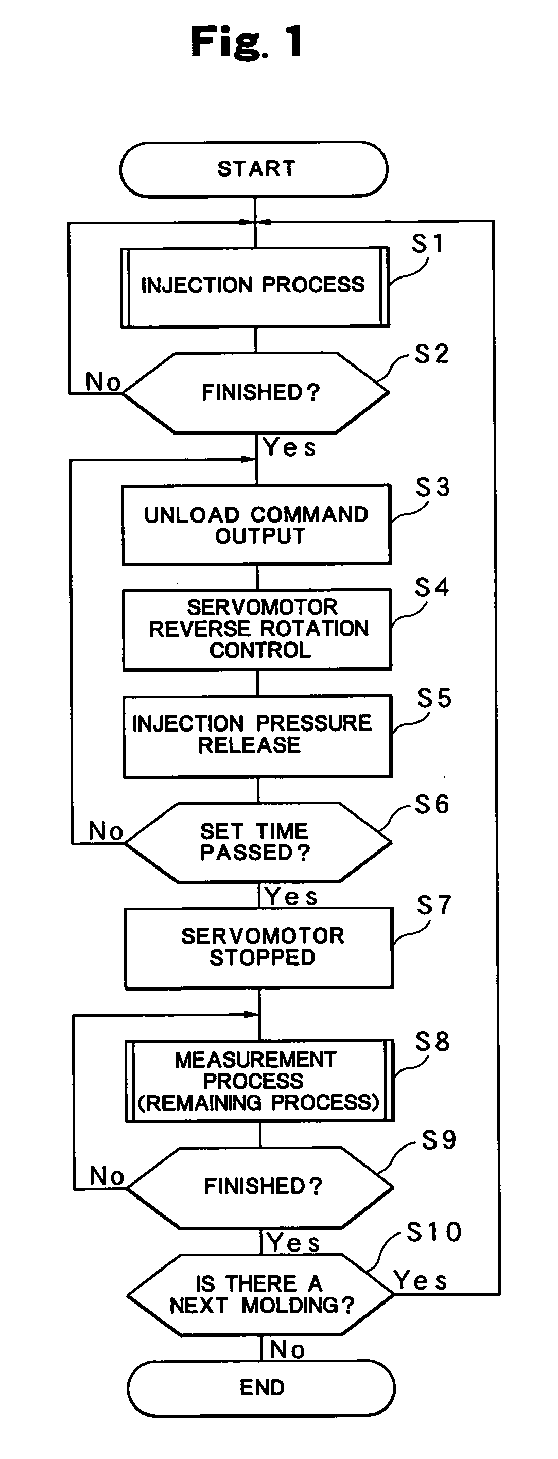
[0017] Next, a preferred embodiment of this invention is introduced and explained in detail based on the drawings. Note that the attached drawings do not specify this invention but serve for facilitating the understanding of this invention. Also, detailed explanations are omitted for commonly-known parts to avoid ambiguity.

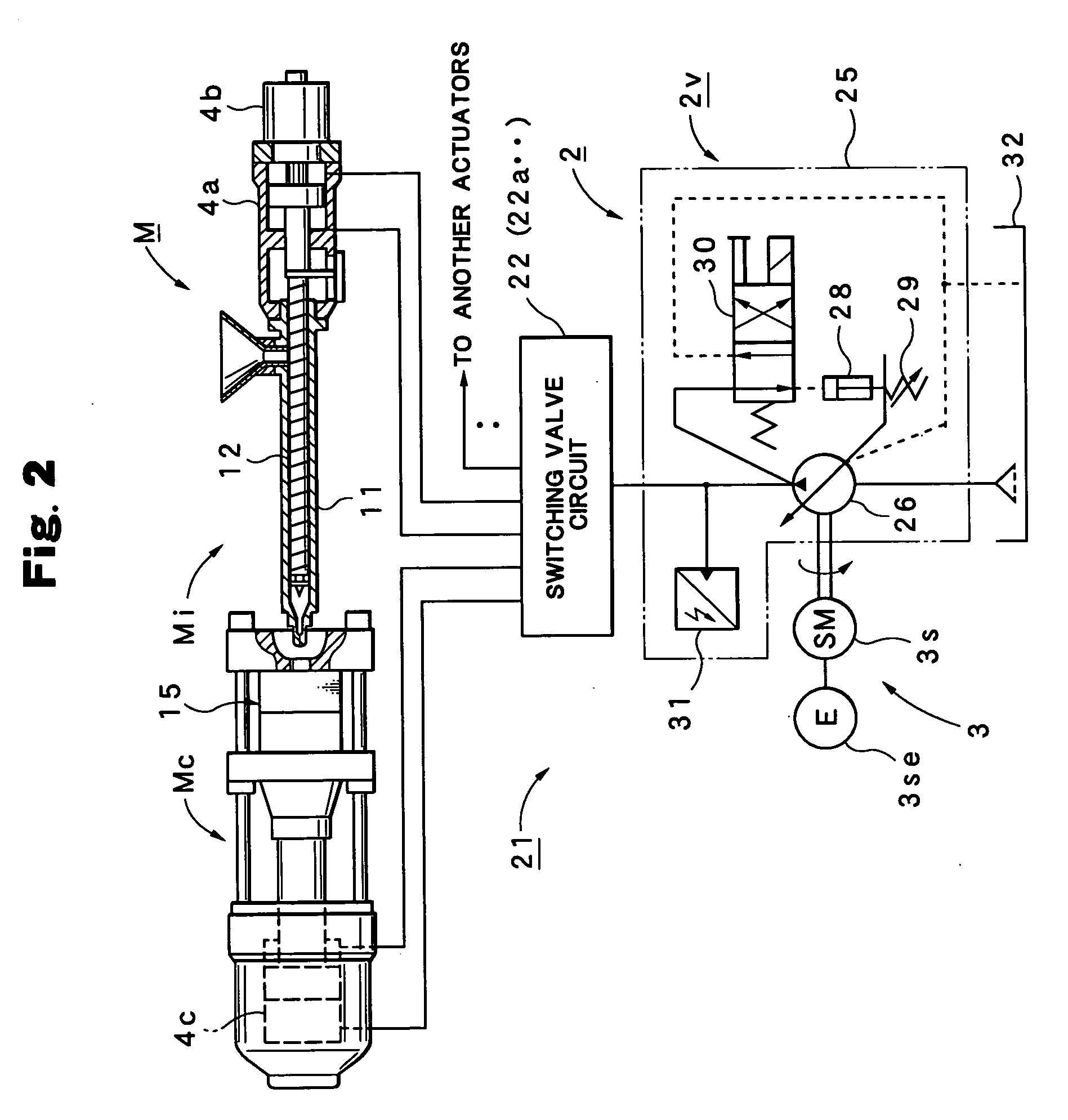
[0018] First, the construction of an injection molding machine M is used in this embodiment with reference to FIG. 2 and FIG. 3.

[0019] In FIG. 2, indicated as M is the injection molding machine equipped with an injector Mi and a clamp. The injection molding machine M is equipped with an injection cylinder 4a which drives a screw 12 built in a heating tube 11 in the injector Mi and a measuring motor (oil motor) 4b which rotates the screw 12 as a hydraulic actuator (4a . . . ), and is equipped with a mold clamping cylinder 4c which opens / closes and clamps a metal mold 15 in the clamp (Mc) and an ejection cylinder 4d (FIG. 3) which ejects a molded product in the me...


PUM

PropertyMeasurementUnit
Pressureaaaaaaaaaa
Flow rateaaaaaaaaaa
Speedaaaaaaaaaa

Abstract

In a method of controlling an injection molding machine M which controls specified operational processes in a molding cycle by variably controlling the rotation speed of a driving motor 3 in a hydraulic pump 2 and driving a specified hydraulic actuators 4a, 4b, . . . , in lowering the pressure Pd of the operational process to a specified pressure Pn, the pressure Pd is forcibly lowered by controlling the driving motor 3 in reverse rotation.

Description

BACKGROUND OF THE INVENTION [0001] 1. Field of the Invention [0002] This invention relates to a method of controlling an injection molding machine which controls specified operational processes by variably controlling the rotation speed of a driving motor of a hydraulic pump. [0003] 2. Description of the Relevant Art [0004] In general, in a hydraulic injection molding machine, a specified hydraulic actuator is driven by a hydraulic driving unit equipped with a hydraulic pump, based on which operational processes are controlled such as a measurement process and an injection process in a molding cycle. Also, when the operational processes are switched, depressurization is performed on the hydraulic actuator so that the switching is performed smoothly and quickly without the behavior of the previous operational process (residual pressure) affecting the next operational process. [0005] Conventionally, known as a method of depressurizing a hydraulic actuator is a method of depressurizing...

Claims


Application Information

Patent Timeline
IPC IPC(8): B29C45/58B29C45/67
CPCB29C45/82B29C2945/76006B29C2945/76391B29C2945/76785B29C2945/76545B29C2945/76605B29C2945/76498
Inventor TANEMURA, DAIKISHIMIZU, KENICHI
Owner NISSEI PLASTIC IND CO LTD
Why Eureka
Try Eureka