Disk drive including means for preventing rotation

a technology of disk drives and rotating means, which is applied in the direction of recording information on magnetic disks, instruments, and recording on them, can solve the problems of difficult control of the stop angle of the rotor b>94, and the difficulty of a dc motor to meet these requirements fully, and achieve the effect of stabilizing and accurate positioning control

Inactive Publication Date: 2005-06-21
PANASONIC CORP
View PDF13 Cites 6 Cited by
  • Summary
  • Abstract
  • Description
  • Claims
  • Application Information

AI Technical Summary

Benefits of technology

[0045]In order to overcome the problems described above, an object of the present invention is to provide a motor controller that can perform a stabilized and accurate positioning control using a DC motor and a method of driving a DC motor.

Problems solved by technology

However, if it is necessary to control the stop angle of the rotor of a DC motor accurately enough or to rotate the motor at an extremely low number of revolutions per minute, it might be difficult for a DC motor to satisfy these requirements fully.
For these reasons, when a DC motor is used, it is difficult to control the stop angle of the rotor 94 accurately enough.
Furthermore, a non-uniform torque is generated around the shaft of a DC motor when power is supplied to the DC motor.
In addition, there is also a great variation in the load applied to a DC motor (e.g., friction caused at the bearing thereof).
In particular, a load variation resulting from the difference between static friction and kinetic friction is a problem.
Thus, in performing a proportional control on a DC motor, such a variation introduces instability into the system.
Consequently, it is particularly difficult to rotate the motor stably at a low velocity.
The rotor has a great moment of inertia, which poses another serious problem.
However, the larger the diameter of the rotor, the greater moment of inertia the rotor has.
Likewise, it is also difficult for the DC motor to stop the load the instant the power that has been supplied to the DC motor is stopped.
However, when such a control mechanism is added to detect the velocity of the load, the cost of a DC motor controller increases.
However, it is still difficult for the objective lens 132 to follow the track accurately just by driving this tracking actuator 141.
Firstly, it is difficult for the conventional optical disk drive to control the rotation of the DC motor at a sufficiently small step angle. Thus, the conventional optical disk drive cannot achieve desired high positioning accuracy. To achieve a high resolution by minimizing the step angle, the pulse voltage applied to the DC motor to drive it may have its amplitude (i.e., the level) or pulse width reduced. However, if the level of the pulse voltage is decreased, then the DC motor will be affected by the variation in load or torque more easily, thus making it difficult to minimize the step angle.
In that case, the motor just vibrates and cannot move the object of control at all.
Accordingly, once such a phenomenon has occurred, it is virtually impossible to minimize the step angle by decreasing the amplitude of the pulse voltage or by shortening the pulse width thereof.
Thus, the conventional control technique cannot increase the positioning accuracy except a very limited situation.
Furthermore, if the braking pulse is applied to the motor just after the driving pulse has been applied thereto, then the stability of control might be decreased significantly.
Also, the load of a driving mechanism is not always the same both in the forward and backward directions.
In the worst-case scenario, even the object of control also moves backward, thus deteriorating the stability of control considerably.
Thus, it is rather imaginable that a braking pulse having such limited voltage value and pulse width is effective insufficiently against the great moment of inertia of the rotor.
However, if the predetermined magnitude of movement is not achieved upon the single application of a pulse voltage having such a small level, then it is highly probable that the object will not move, either, no matter how many times the same small pulse voltage is applied to the motor.

Method used


Image

  • Disk drive including means for preventing rotation
  • Disk drive including means for preventing rotation
  • Disk drive including means for preventing rotation

Examples


embodiment 1

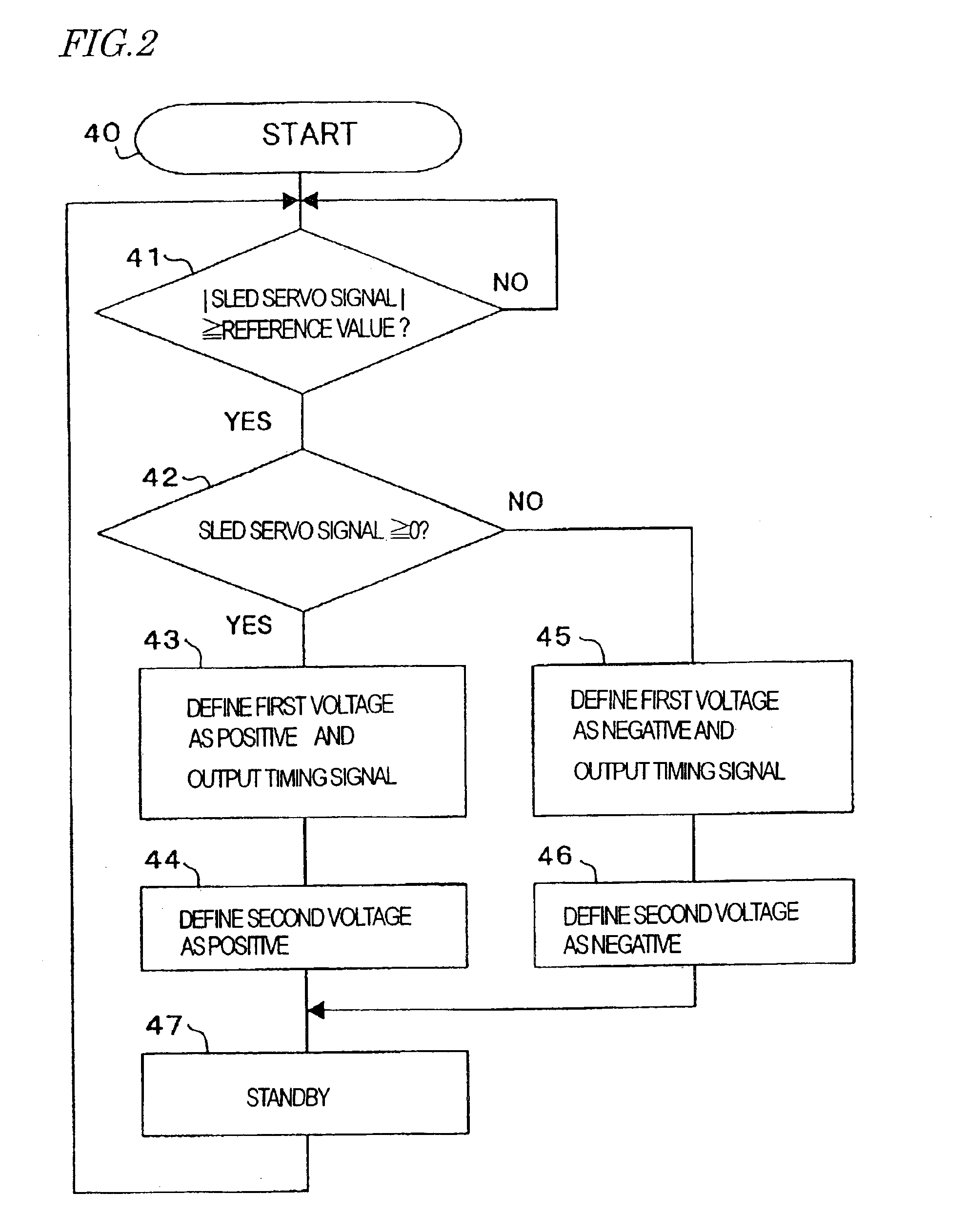
[0080]Hereinafter, a motor controller according to a first specific preferred embodiment of the present invention will be described with reference to the accompanying drawings.

[0081]FIG. 1 schematically illustrates the main section of an optical disk drive 1 including the motor controller of the first preferred embodiment. The optical disk drive 1 may be used to read and / or write information from / on an optical disk 2 such as a DVD-RAM, on which spiral tracks are formed.

[0082]The optical disk drive 1 includes a rotating / driving mechanism for use to rotate the optical disk 2 that has been mounted thereon. The rotating / driving mechanism includes spindle motor 9, turntable 25 and driver (not shown). The turntable 25 is fitted with the shaft 24 of the spindle motor 9 to mount the optical disk 2 thereon. The driver is used to drive the spindle motor 9.

[0083]The optical disk drive 1 further includes optical head (or optical pickup) 23, optical head moving mechanism 12 and DC motor 5. The o...

embodiment 2

[0140]Hereinafter, a motor controller according to a second specific preferred embodiment of the present invention will be described with reference to the accompanying drawings.

[0141]FIG. 5 schematically illustrates the main section of an optical disk drive 1a including a motor controller according to the second preferred embodiment. In FIG. 5, each component of the optical disk drive 1a having substantially the same function as the counterpart of the optical disk drive 1 is identified by the same reference numeral.

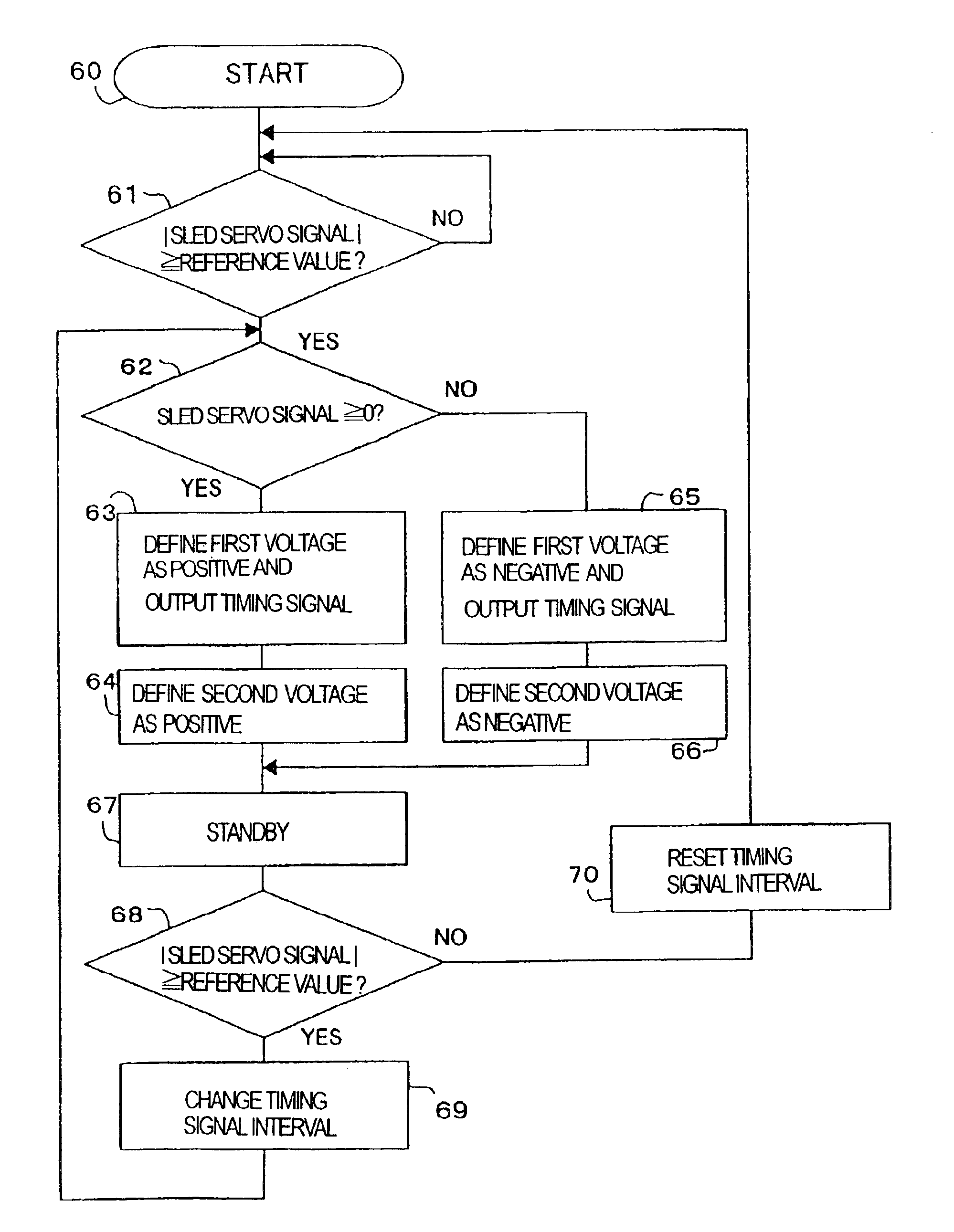
[0142]Unlike the optical disk drive 1 of the first preferred embodiment described above, the optical disk drive 1a of the second preferred embodiment includes a control unit 19a having a timing changer 32. Thus, the following description of the second preferred embodiment will be focused on the operation of the control unit 19a.

[0143]As shown in FIG. 5, the control unit 19a includes the timing generator 20 and the timing changer 32. The timing changer 32 changes the inte...


PUM

PropertyMeasurementUnit
stop angleaaaaaaaaaa
velocityaaaaaaaaaa

Abstract

A motor controller includes DC motor, driving mechanism, voltage generator circuit and control unit. The driving mechanism moves an object having a predetermined mass against a load applied to the object and by transmitting a rotational force of the motor to the object. The voltage generator circuit generates first and second voltages. The first voltage is high enough to rotate the motor to such a degree as to get the object moved by the driving mechanism. The second voltage has the same polarity as the first voltage and has such amplitude as to prevent the motor from rotating either in a backward direction due to a cogging torque or in a forward direction. The control unit controls the voltage generator circuit in such a manner that the voltage generator circuit applies the second voltage to the motor after having applied the first voltage to the motor.

Description

CROSS-REFERENCE TO RELATED APPLICATIONS[0001]This application is a divisional of U.S. patent application Ser. No. 10 / 195,086, filed Jul. 12, 2002 now U.S. Pat. No. 6,759,824. The enumerated prior application is hereby incorporated in its entirety.FIELD OF THE INVENTION[0002]The present invention generally relates to a motor controller and more particularly relates to an apparatus for performing an accurate positioning control by using a DC motor of a small size and a method of driving a DC motor.DESCRIPTION OF THE RELATED ART[0003]A DC motor including a brush and a commutator has a simple structure and can be manufactured at a low cost. Also, a DC motor achieves high efficiency and high output although its size is small, and needs no special driver. For these reasons, a DC motor is now used in numerous appliances.[0004]However, if it is necessary to control the stop angle of the rotor of a DC motor accurately enough or to rotate the motor at an extremely low number of revolutions pe...

Claims


Application Information

Patent Timeline
Patent Type & Authority Patents(United States)
IPC IPC(8): G11B19/20G11B7/085
CPCG11B7/08529G11B19/20G11B7/08582
Inventor KAWABATA, TORUMUSHIKA, YOSHIHIRO
Owner PANASONIC CORP
Why Eureka
Try Eureka