Supercritical fluid conveying device

A supercritical fluid and delivery device technology, applied in the direction of gas/liquid distribution and storage, pipeline systems, mechanical equipment, etc., can solve problems such as complex structure design, control lag, and influence on experimental technology, so as to improve work efficiency and stabilize transportation Effects with precise control and simple operation

Inactive Publication Date: 2015-01-14
NINGBO UNIV
View PDF7 Cites 8 Cited by
  • Summary
  • Abstract
  • Description
  • Claims
  • Application Information

AI Technical Summary

Problems solved by technology

[0004] The Chinese invention patent application with the patent application number 201110159337.3 "A Constant Pressure and Constant Flow Injection Device for Micro-Flow High-Pressure Liquefied Gas" (application publication number CN102310515A) discloses a constant-pressure and constant-flow injection device for micro-flow high-pressure liquefied gas. Including the gas pressurization liquefaction part, gas output part, pressure flow control part and pressure flow feedback part, the injection device of this invention uses a linear reciprocating mechanism for continuous gas output control, but because the system pipeline is too long, the control lags and the output The end pressure fluctuates, and the stable delivery of gas cannot be realized, which directly affects the subsequent experimental process.
[0005] The Chinese invention patent application "A Supercritical Fluid Injection Device" (application publication number CN102310516A) with the patent application number 201110253685.7 discloses a supercritical fluid injection device, which consists of a gas cooling pre-pressurization part, a supercritical fluid forming part, and The pressure temperature flow feedback part and the control part are composed, but because the injection device uses multiple booster pumps, the structural design is complex and the noise is relatively high, so it is not suitable for industrial production practice

Method used


Image

  • Supercritical fluid conveying device
  • Supercritical fluid conveying device

Examples


Embodiment Construction

[0023] The present invention will be further described in detail below in conjunction with the accompanying drawings and embodiments.

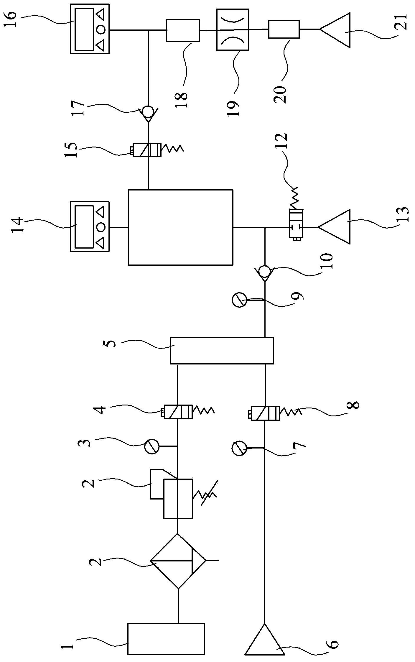
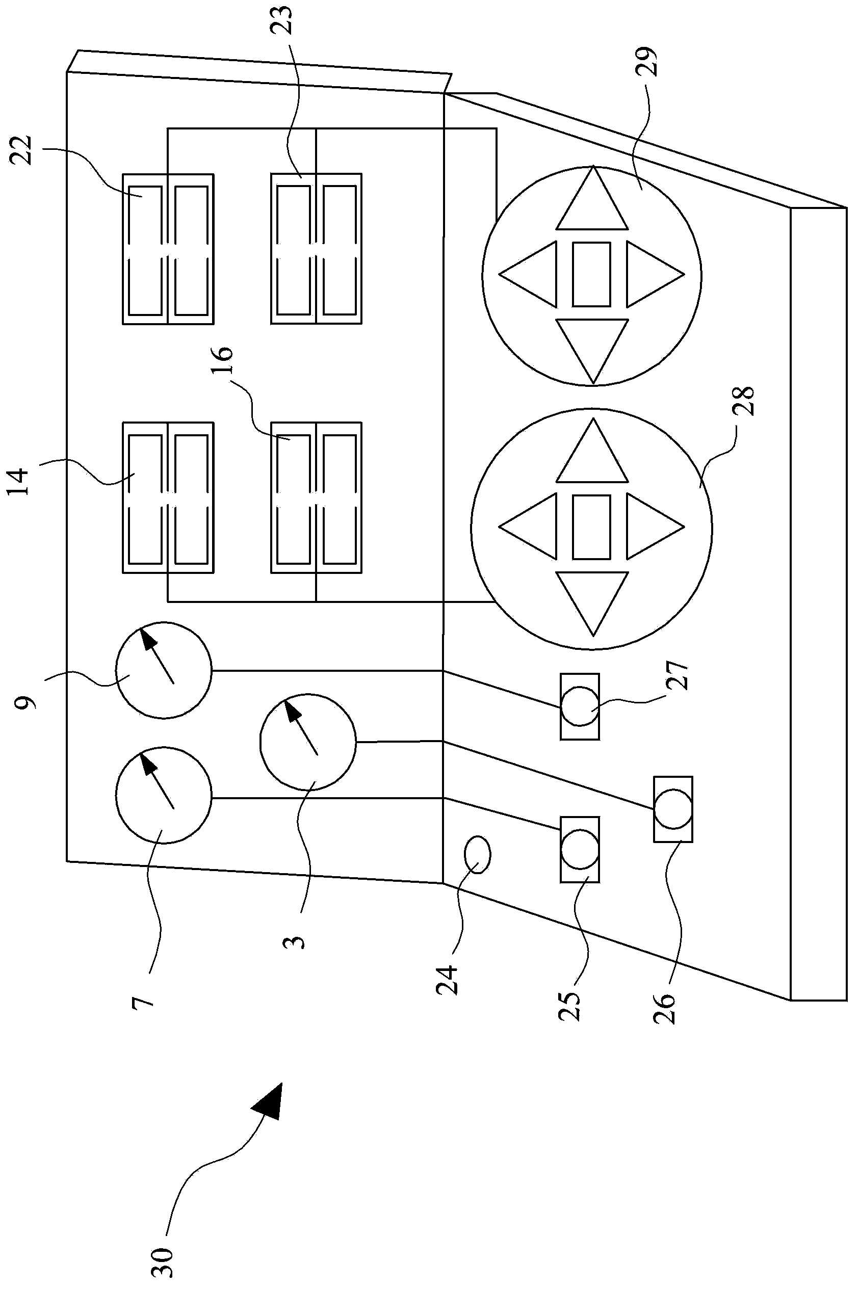
[0024] figure 1 and figure 2 The supercritical fluid delivery device of this embodiment includes a gas source control device, a pressurization control device, a storage device and an electric control device. The air source control device is composed of an air source 6, an intake pressure gauge 7 and an intake air on-off solenoid valve 8, wherein the intake air pressure gauge 7 is located between the air source 6 and the intake air on-off solenoid valve 8, and the air source 6 is carbon dioxide Or a blend of nitrogen or carbon dioxide and nitrogen in any proportion. The supercharging control device is connected in sequence by a low-noise air compressor 1, a filter decompression air source triple unit 2, an air pressure gauge 3, an on-off solenoid valve 4, a booster pump 5, a high-pressure pressure gauge 9 and a first check valve 10 At the s...


PUM


Abstract

The invention discloses a supercritical fluid conveying device which comprises a gas source control device, a pressurization control device, a storage device and an electric control device. The gas source control device mainly comprises a gas source, a gas inlet pressure meter and a gas inlet on-off electromagnetic valve. The pressurization control device mainly comprises a low-noise air compressor, a filtering-pressure reduction-gas source triple piece, an air pressure meter, an on-off electromagnetic valve, a pressurization pump, a high-pressure pressure meter and a check valve. The storage device mainly comprises a high-pressure gas storage tank, a pressure sensor, an overpressure overflow electromagnetic valve and a check valve; the electric control device realizes the control over the whole system mainly by means of an integrated control panel. The supercritical fluid conveying device has the advantage that a supercritical fluid can be stably conveyed and controlled and the working efficiency is greatly improved.

Description

technical field [0001] The invention relates to a fluid conveying device, in particular to a supercritical fluid conveying device, which is used in systems that have strict requirements on gas injection pressure, flow rate, etc., such as polymer supercritical microcellular foaming. Background technique [0002] As we all know, when a substance is near the critical point, the physical properties of all fluids, such as density, viscosity, solubility, heat capacity, and dielectric constant, will change rapidly. When the temperature of the substance is higher than the critical temperature and the pressure is higher than the critical pressure, the substance is in a supercritical state. Supercritical fluid is above the critical temperature and critical pressure, between gas and liquid, and has the dual properties and advantages of gas and liquid: strong solubility, good diffusion performance and easy control. Near the critical point, small changes in pressure and temperature can ...

Claims


Application Information

Patent Timeline
Patent Type & Authority Applications(China)
IPC IPC(8): B29C44/34B29C44/60F17D1/14
Inventor 陈忠仁包锦标刘智峰
Owner NINGBO UNIV
Why Eureka
Try Eureka