Cleaner head

a cleaning head and cleaning head technology, applied in the direction of suction cleaners, cleaning equipment, suction nozzles, etc., can solve the problems of affecting the performance of the front agitator, and achieve the effect of improving the performance of the cleaner head and increasing the resistance to the manoeuvring of the cleaner head

Active Publication Date: 2014-06-10
DYSON TECH LTD
View PDF13 Cites 27 Cited by
  • Summary
  • Abstract
  • Description
  • Claims
  • Application Information

AI Technical Summary

Benefits of technology

[0012]The rear agitator is arranged so that the surface engaging means of the rear agitator can dislodge matter from the pile of the front agitator, which can prevent debris such as hair from becoming entangled within the pile of the front agitator and causing the pile to become locally flattened, thereby impairing the performance of the front agitator. We have also found that any matter entangled within the pile of the front agitator during use of the cleaner head on a hard floor surface can be readily transferred to a carpeted floor surface when the cleaner head is manoeuvred on to such a surface while the agitators are rotating. For example, the front agitator and the rear agitator may be arranged so that the surface engaging means of the rear agitator penetrate the pile of the front agitator so that, during rotation of the agitators, the surface engaging means of the rear agitator pass through, or “comb”, the pile of the front agitator to dislodge matter from the pile. The maximum distance by which the surface engaging means of the rear agitator penetrate the pile of the front agitator is preferably in the range from 0.5 to 2 mm so that the surface engaging means of the rear agitator do not impede undesirably the rotation of the front agitator.
[0031]Preferably, the main body comprises a front edge located above the rotational axis of the front agitator and the pile of the front agitator extends forwardly beyond the front edge of the main body. By exposing a front portion of the front agitator, the pile of the exposed front portion of the front agitator can function as a relatively soft and flexible front bumper of the cleaner head. Furthermore, the cleaner head can be pushed up against a wall item of furniture or other upstanding object so that the pile of the front agitator can sweep dirt and debris from the parts of the floor surface which adjoin that object. Therefore, in a third aspect the present invention provides a cleaner head for a vacuum cleaning appliance, comprising a main body, a front agitator and a rear agitator, each agitator being rotatable relative to the main body, and means for rotating the front agitator and the rear agitator, wherein the main body comprises a front edge located above the rotational axis of the front agitator and the front agitator comprises a pile which extends forwardly beyond the front edge of the main body.

Problems solved by technology

The rear agitator is arranged so that the surface engaging means of the rear agitator can dislodge matter from the pile of the front agitator, which can prevent debris such as hair from becoming entangled within the pile of the front agitator and causing the pile to become locally flattened, thereby impairing the performance of the front agitator.

Method used


Image

  • Cleaner head
  • Cleaner head
  • Cleaner head

Examples


Embodiment Construction

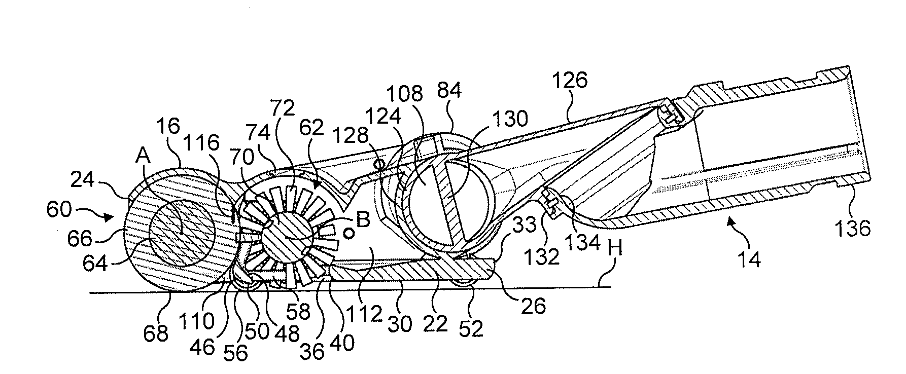
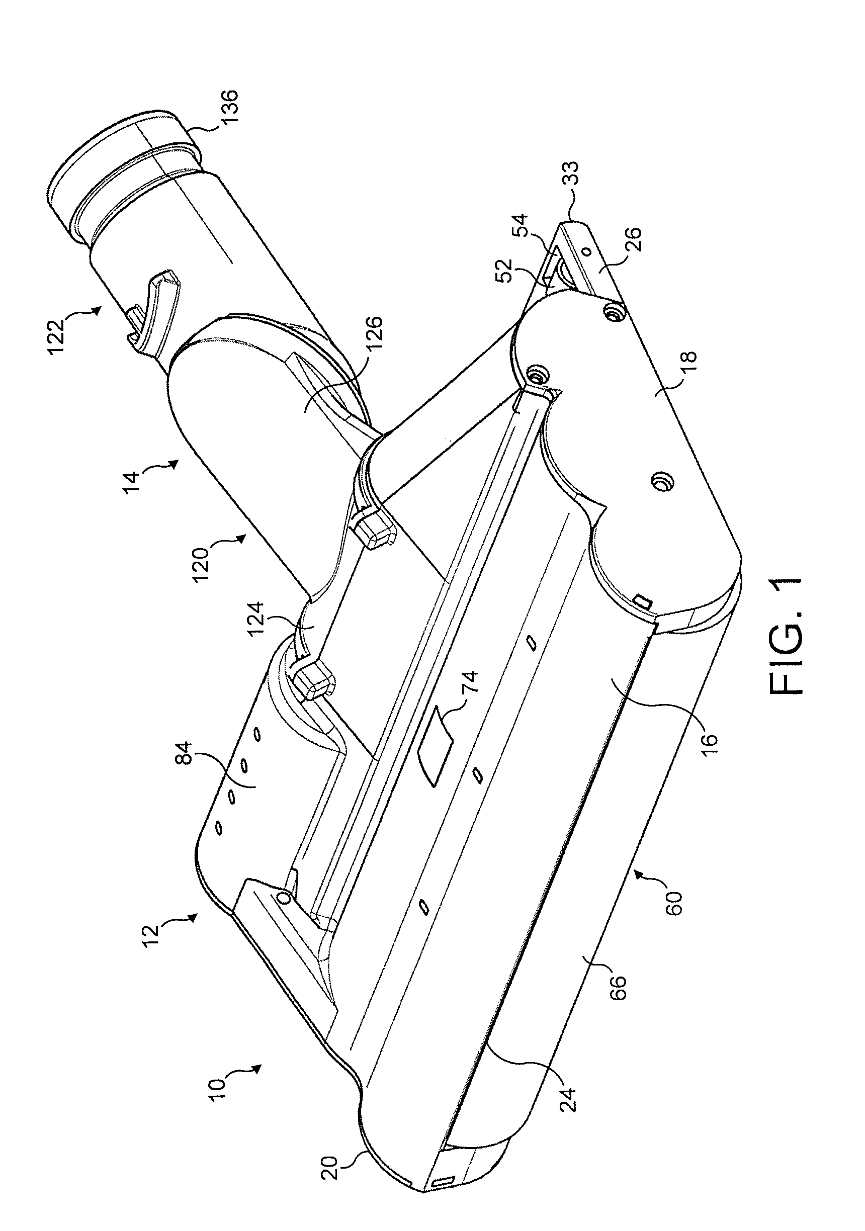
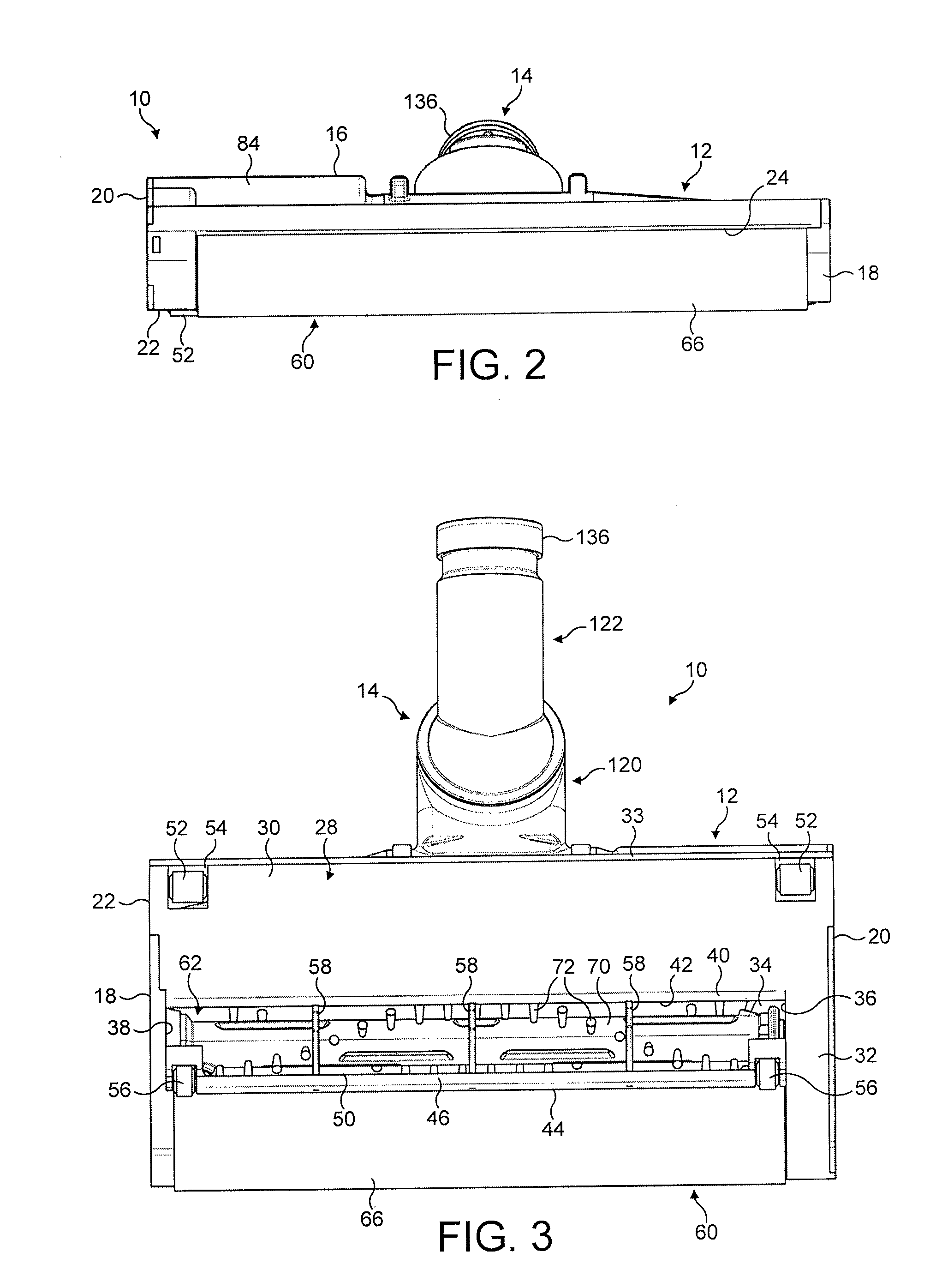
[0045]FIGS. 1 to 4 and FIG. 6 illustrate an embodiment of a cleaner head 10 for a vacuum cleaning appliance. In this embodiment, the cleaner head 10 is arranged to be connectable to a wand or hose of a cylinder vacuum cleaning appliance. The cleaner head 10 comprises a main body 12 and a conduit 14 connected to the main body 12. The main body 12 comprises an upper section 16, side plates 18, 20 and a lower section 22. The upper section 16 may be integral with the lower section 22, with the side plates 18, 20 being connected to the upper section 16 and the lower section 22 of the main body 12. The upper section 16 of the main body 12 has a raised front edge 24. A rear portion 26 of the lower section 22 of the main body 12 protrudes rearwardly beyond the upper section 16 of the main body 12.

[0046]The lower section 22 of the main body 12 comprises a bottom surface 28 which, in use, faces a floor surface to be cleaned and, as described in more detail below, engages the surface of a carp...


PUM


Abstract

A cleaner head for a vacuum cleaning appliance includes a main body having a downwardly-directed suction opening and at least one surface engaging support member, a front agitator and a rear agitator, with each agitator being rotatable relative to the main body, and a mechanism for rotating the front agitator and the rear agitator. The front agitator has a relatively flexible pile and the rear agitator has relatively stiff bristles arranged to dislodge matter from the pile of the front agitator. The pile of the front agitator and the at least one surface engaging support member extend downwardly beyond the bristles of the rear agitator so as to space the bristles of the rear agitator from a relatively hard surface to be cleaned.

Description

REFERENCE TO RELATED APPLICATIONS[0001]This application is a national stage application under 35 USC 371 of International Application No. PCT / GB2010 / 052009, filed Dec. 2, 2010, which claims the priority of United Kingdom Application No. 1000257.4, filed Jan. 8, 2010, and United Kingdom Application No. 1000259.0, filed Jan. 8, 2010, the entire contents of which are incorporated herein by reference.FIELD OF THE INVENTION[0002]The present invention relates to a cleaner head for a vacuum cleaning appliance.BACKGROUND OF THE INVENTION[0003]A vacuum cleaner typically comprises a main body containing dirt and dust separating apparatus, a cleaner head connected to the main body and having a suction opening, and a motor-driven fan unit for drawing dirt-bearing air through the suction opening. The suction opening is directed downwardly to face the floor surface to be cleaned. The dirt-bearing air is conveyed to the separating apparatus so that dirt and dust can be separated from the air befor...

Claims


Application Information

Patent Timeline
Patent Type & Authority Patents(United States)
IPC IPC(8): A47L9/04
CPCA47L9/04A47L9/0488
Inventor ILES, JEAN-PAUL MARKARTHEY, SPENCER JAMES ROBERTMAGUIRE, SCOTT ANDREW
Owner DYSON TECH LTD
Why Eureka
Try Eureka