Method and apparatus for controlling transmission power in WLAN system

a transmission power and wireless lan technology, applied in power management, high-level techniques, wireless commuication services, etc., can solve the problems of reducing the throughput efficiency and signal collision may occur, and the power consumption efficiency of a wireless station may become a problem, so as to achieve the effect of maintaining communication performance and improving power consumption efficiency

Active Publication Date: 2014-06-10
ELECTRONICS & TELECOMM RES INST
View PDF8 Cites 13 Cited by
  • Summary
  • Abstract
  • Description
  • Claims
  • Application Information

AI Technical Summary

Benefits of technology

[0010]An embodiment of the present invention is directed to a transmit power control method and apparatus in a WLAN system, which is capable of improving power consumption efficiency while maintaining communication performance.
[0011]Another embodiment of the present invention is directed to a transmit power control method and apparatus in a WLAN system, which is capable of solving a hidden node problem and a problem caused by an OBSS.

Problems solved by technology

When a portable device uses the maximum transmit power, the power consumption efficiency of a wireless station may become a problem.
The hidden node problem occurs when a signal transmitted from a specific station within a basic service set suffers from a path loss caused by a channel and does not approach the receive sensitivity of another station.
Furthermore, as another station attempts to transmit a signal, signal collision may occur.
During frequent data communication processes, the exchange of RTS and CTS frames using the maximum transmit power may serve as a main factor which reduces the throughput efficiency and power consumption efficiency of a wireless station.
Therefore, it is expected that the interference problem will be serious in the next-generation WLAN system.

Method used


Image

  • Method and apparatus for controlling transmission power in WLAN system
  • Method and apparatus for controlling transmission power in WLAN system
  • Method and apparatus for controlling transmission power in WLAN system

Examples


Embodiment Construction

[0025]Exemplary embodiments of the present invention will be described below in more detail with reference to the accompanying drawings. The present invention may, however, be embodied in different forms and should not be constructed as limited to the embodiments set forth herein. Rather, these embodiments are provided so that this disclosure will be thorough and complete, and will fully convey the scope of the present invention to those skilled in the art. Throughout the disclosure, like reference numerals refer to like parts throughout the various figures and embodiments of the present invention.

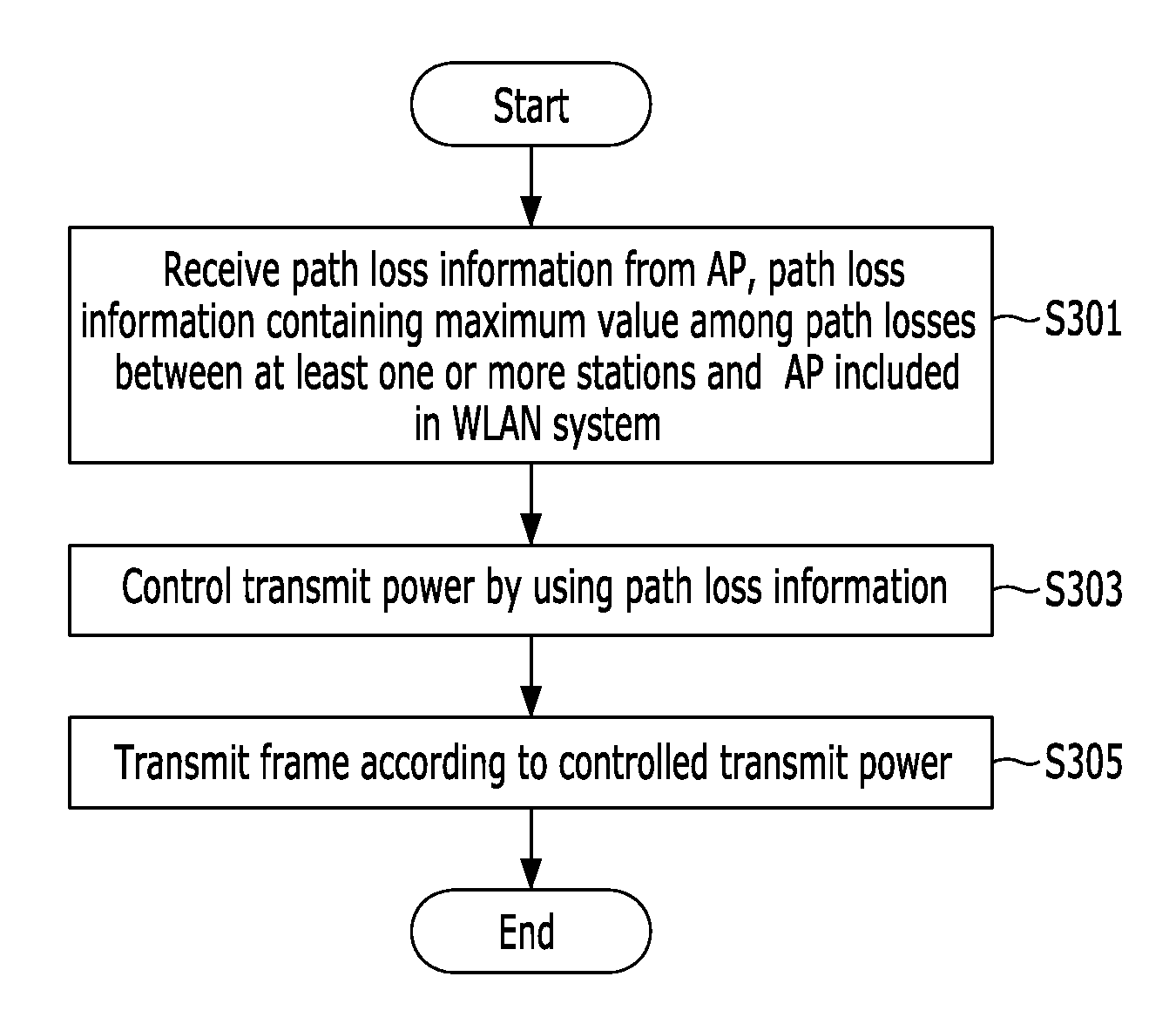
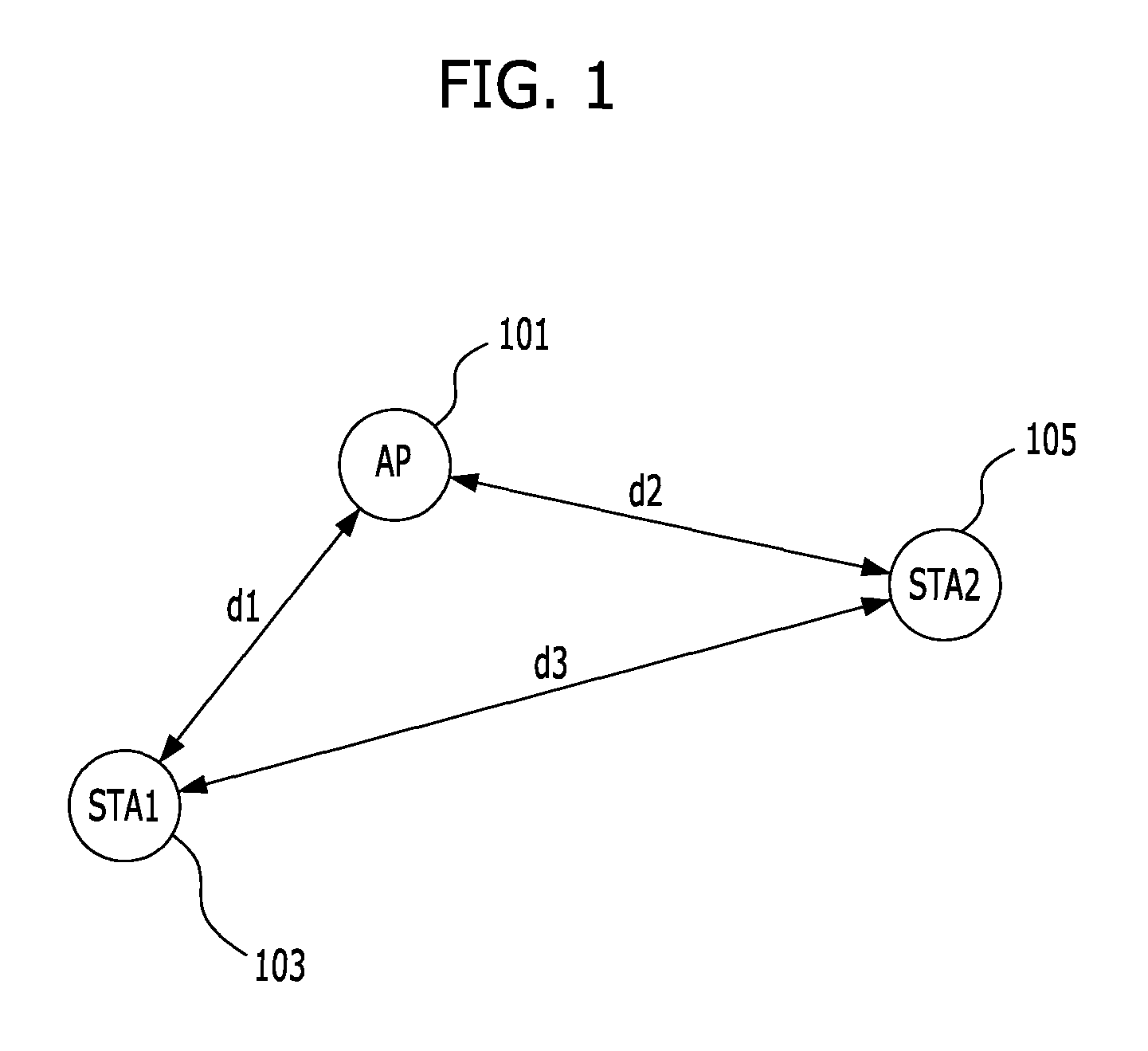
[0026]A transmit power control method and apparatus in accordance with an embodiment of the present invention controls a transmit power by using a path loss between an AP and a station. As the path loss is used, a frame does not need to be transmitted at the maximum power, but the transmit power may be controlled to transmit a frame.

[0027]For example, when a first station knows a path loss...


PUM


Abstract

A transmit power control method of a first station in a wireless LAN (WLAN) system includes: receiving path loss information from an (access point) AP, the path loss information containing a maximum value among path losses between the AP and at least one or more stations included in the WLAN system; controlling a transmit power by using the path loss information; and transmitting a frame according to the controlled transmit power. In said controlling the transmit power by using the path loss information, the transmit power is controlled by using a path loss obtained by adding the maximum value and a path loss between the first station and the AP or by using the path loss between the first station and the AP.

Description

CROSS-REFERENCE(S) TO RELATED APPLICATIONS[0001]The present application claims priority of Korean Patent Application No. 10-2009-0101232, filed on Oct. 23, 2009, which is incorporated herein by reference in its entirety.BACKGROUND OF THE INVENTION[0002]1. Field of the Invention[0003]Exemplary embodiments of the present invention relate to a transmit power control method and apparatus in a wireless LAN (WLAN) system; and, more particularly, to a transmit power control method and apparatus which controls a transmit power by using a path loss between a station and an access point (AP) in a WLAN system.[0004]2. Description of Related Art[0005]In a wireless communication device, a transmission terminal requires 2-2.5 times larger power consumption than a reception terminal, and the power consumption required by the transmission terminal depends significantly on the magnitude of transmit power. In general, a commercial wireless LAN device focuses on the transmission performance rather tha...

Claims


Application Information

Patent Timeline
Patent Type & Authority Patents(United States)
IPC IPC(8): H04W4/00
CPCH04W52/267H04W52/242Y02B60/50H04W52/243H04W24/08H04W84/12Y02D30/70
Inventor LEE, IL-GUCHOI, JEEYONLEE, SOK-KYU
Owner ELECTRONICS & TELECOMM RES INST
Why Eureka
Try Eureka