Controller of hybrid vehicle

A technology for control devices and hybrid locomotives, applied in control devices, engine control, hybrid vehicles, etc., can solve the problems of power transmission system transmission efficiency reduction, reduction of regenerative energy, temperature reduction, etc., to increase fuel consumption efficiency and improve regeneration efficiency effect

Inactive Publication Date: 2004-09-08
HONDA MOTOR CO LTD
View PDF1 Cites 13 Cited by
  • Summary
  • Abstract
  • Description
  • Claims
  • Application Information

AI Technical Summary

Problems solved by technology

[0005] However, the structure of the drive system having a clutch between the engine and the motor has the following problems: the applicability of this drive system to different kinds of locomotives is limited due to the complicated structure of the system, and even in this The transmission efficiency of the power transmission system of this drive system is reduced when the locomotive is running
[0006] In such a drive system where the engine, motor and transmission are all connected in series, there is a problem that the amount of regenerative energy is reduced due to friction of the aforementioned engine, thereby limiting the amount of motor acceleration
However, when the intake and exhaust valves are fully open as described above, fresh air enters the exhaust system during deceleration so that the temperature of the catalyst and A / F (air-fuel ratio) sensor decreases, which causes problems with exhaust gas The optimal control quality degrades

Method used


Image

  • Controller of hybrid vehicle
  • Controller of hybrid vehicle
  • Controller of hybrid vehicle

Examples


Embodiment Construction

[0043] Hereinafter, a first embodiment of the present invention is described with reference to the drawings.

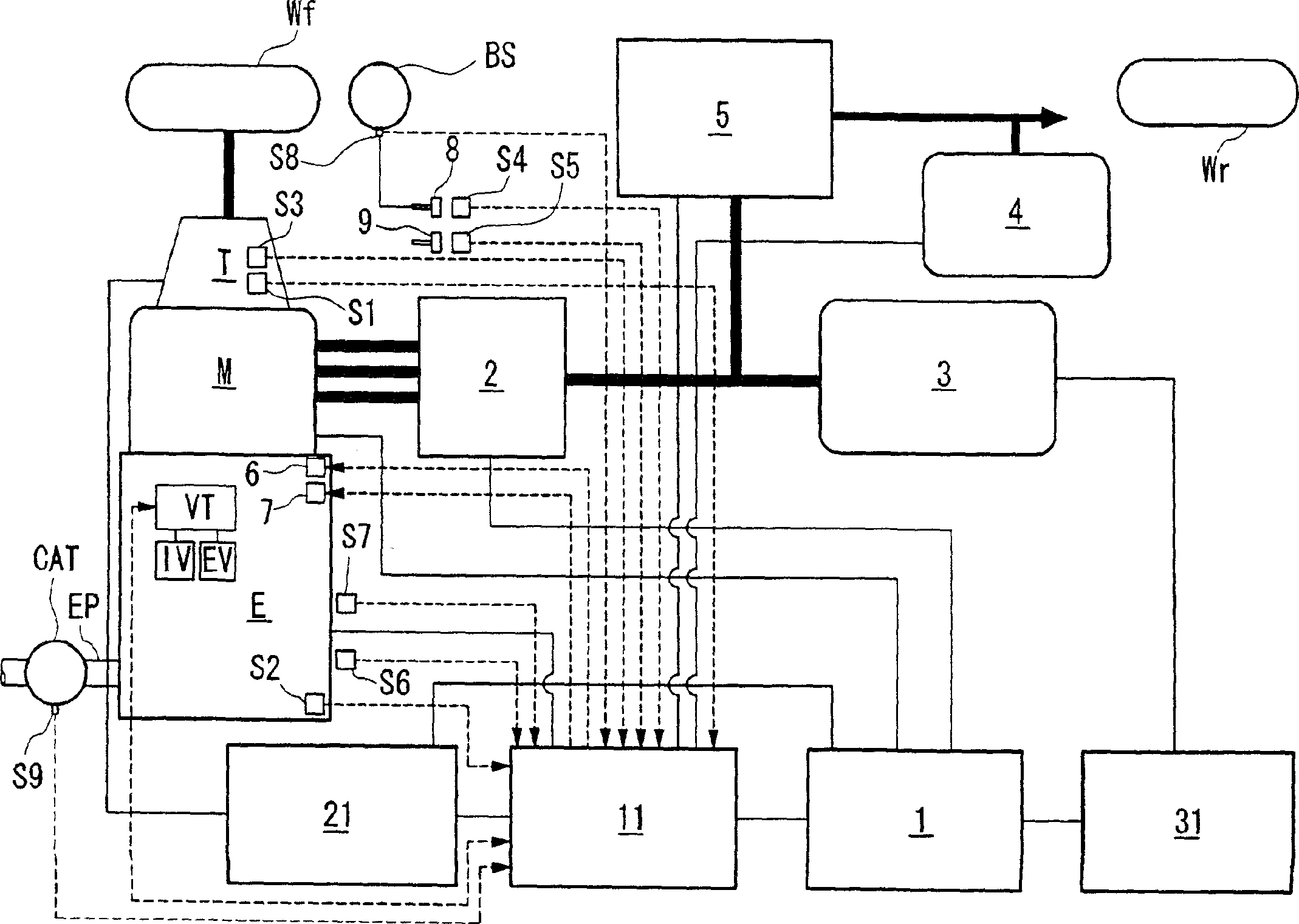
[0044] attached figure 1 A schematic drawing showing the general structure of a hybrid locomotive is shown. as attached figure 1 As shown, the drive system is formed by connecting an engine E, a motor M and a transmission T in series. Therefore, no clutch is provided between the engine E and the motor M. The driving force of the engine E and the motor M is transmitted to front wheels Wf and Wf as drive wheels through a transmission T (for example, an automatic transmission or a manual transmission). In contrast, during deceleration of a hybrid locomotive, driving force is output from the front wheels, and the motor M operates as a generator that generates regenerative braking energy and recovers kinetic energy of the locomotive as electrical energy. Note that the symbol Wr indicates the rear wheel.

[0045] The driving of the motor M and the regenerative operat...


PUM


Abstract

A control device for a hybrid vehicle having an engine and a motor as driving sources for the vehicle, and when decelerating, the control device stops the fuel supply to the engine and generates energy by regenerative braking. The engine is a cylinder pause-type engine which is capable of switching between the all-cylinder driving state in which all of cylinders are operating, and a cylinder paused driving state in which all of the cylinders are paused, and the control device of the hybrid vehicle comprises a cylinder pause state determination device for determining whether the engine is in the all cylinder driving state or in a cylinder paused driving state and a regeneration amount supplementing device for supplementing the regeneration energy by the motor by use of the increment of the regeneration energy obtained during the cylinder pausing operation than that obtained during all cylinder driving state.

Description

technical field [0001] The present invention relates to a control system of a hybrid locomotive, in particular to a control system of a hybrid locomotive capable of improving fuel consumption efficiency. Background technique [0002] Generally, a well-known hybrid vehicle has a motor as a power source for driving in addition to an engine. Hybrid locomotives can be divided into serial hybrid locomotives and parallel hybrid locomotives. In a parallel hybrid locomotive, a motor connected to the engine facilitates rotation of the engine's drive shaft while using the motor as a generator to charge the power storage unit. [0003] In parallel hybrid locomotives, the motor boosts the engine during acceleration and charges a power storage unit such as a battery during deceleration through deceleration regeneration to maintain sufficient electrical energy (hereinafter referred to as residual charge) in the power storage unit such as the battery or "state of charge") to meet the dri...

Claims


Application Information

Patent Timeline
Patent Type & Authority Applications(China)
IPC IPC(8): F01L13/00B60K6/20B60K6/485B60K6/54B60L50/16B60W10/06B60W10/08B60W20/00F01L1/26F02D13/02F02D13/04F02D13/06F02D17/02F02D29/02F02D41/02F02D41/04F02D41/36F02D45/00
CPCY02T10/6286Y02T10/6226B60W2540/12F02D2200/0406B60W2550/12F02N11/10Y02T10/7005F02D41/0087F01L2105/00F02D2250/41F02N11/006B60K6/543F01L2800/00F01L2800/13Y02T10/6221Y02T10/52F02D2200/0802F02D13/04B60W2710/0605Y02T10/48B60K6/48Y02T10/47F02D2041/0012F02D17/02B60W10/18F02N2200/023B60W20/00B60W10/06F01L1/267F01L1/022B60K6/485F01L2103/01Y02T10/7077F02D41/123F02N11/0818B60W2555/20F01L2303/01F01L2305/00Y02T10/40Y02T10/62B60W30/18127B60W20/13
Inventor 若城辉男高桥秀幸松原笃加茂智治佐藤利行中本康雄
Owner HONDA MOTOR CO LTD
Why Eureka
Try Eureka