Fastening device for a collector of solid remains swiveling at the end of a mobile arm in particular fastening device for articulated buckets of a crust shovel

Inactive Publication Date: 2014-06-24
E-CL
View PDF13 Cites 0 Cited by
  • Summary
  • Abstract
  • Description
  • Claims
  • Application Information

AI Technical Summary

Benefits of technology

[0059]Another subject according to the invention is a bucket support designed to work in conjunction with the fastening device for simultaneous fastening of buckets placed opposite each other as described previously. It is characterized in that it includes means to support and maintain in position two buckets placed substantially symmetrically in relation to a vertical plane P1, in a geometrical configuration where the buckets are open, the opening angle being such that, after removing the pins, and after a slight rotation in the opening direction which releases the first fixing means from the second fixing means, a vertical movement at the top of the mobile arm can be made to move away the pivot-members without actuating said buckets. In this way, old buckets can be detached by gravity alone, without having to use another means to retain said buckets. The means of support which make it possible to direct and maintain the buckets in a precise angular position may, for example, be V-notches worked into the uprights of the support and on which the parts of the buckets whose section matches the complementary s

Problems solved by technology

But it is extremely hard and adheres to the wall of the anode block, so that it proves to be necessary to break it around the worn anode, in order for the latter to be extracted.
Breaking up the crust and handling the worn anode block inevitably generate the formation of solid pieces or parts which float on, or remain in suspension in the liquid medium made up by the electrolyte bath and the molten metal, or which fall to the bottom of the tank.
In addition, mud settles gradually to the bottom of the tank, i.e. on the cathode, forming an increasingly thick layer, which increa

Method used


Image

  • Fastening device for a collector of solid remains swiveling at the end of a mobile arm in particular fastening device for articulated buckets of a crust shovel
  • Fastening device for a collector of solid remains swiveling at the end of a mobile arm in particular fastening device for articulated buckets of a crust shovel
  • Fastening device for a collector of solid remains swiveling at the end of a mobile arm in particular fastening device for articulated buckets of a crust shovel

Examples


Example

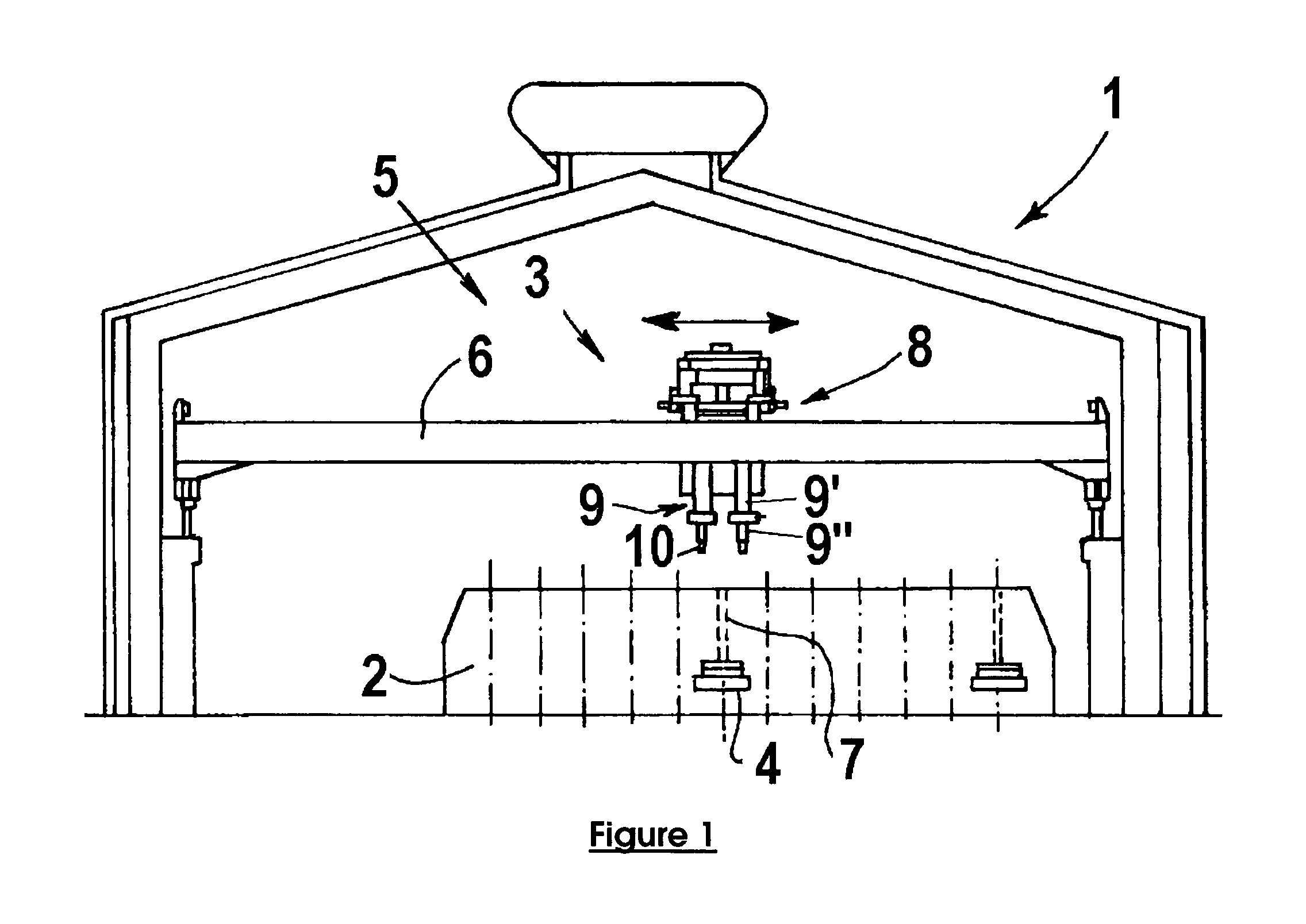
[0068]Electrolysis plants for the production of aluminum include a liquid aluminum production area containing one or more electrolysis halls. The electrolysis hall (1) illustrated in FIG. 1 comprises electrolysis cells (2) and a service machine (5). The electrolysis cells (2) are normally laid out in row or files, each row or file typically comprising over a hundred cells. The cells (2) are laid out so as to leave an aisle along the electrolysis hall (1). Cells (2) include a series of anodes (4) provided with a metal stem (7) for fixing the anodes and connecting them electrically to a metal anode frame (not shown).

[0069]The service unit (5) is used to carry out operations on the cells (2) such as changing anodes or filling the feed hoppers with crushed melt and aluminum fluoride (AlF3). It can also be used to handle various loads, such as tank parts, ladles of liquid metal used during tapping (“tapping ladles”) or anodes. It can also be used to clean the anode hole, after the remova...


PUM


Abstract

Fastening device designed to fasten a collecting container including: at least one pivot-member assembled so as to swivel around an axis on a mobile arm and including at least one first transverse arm provided with a first fixing structure and at least one second transverse arm provided with axial bores, at least two fasteners fixed onto the collecting container, the first fastener being provided with a second fixing structure working in conjunction with the first fixing structure, the second fastener, provided with axial bores, and a pin, designed to be inserted and to slide inside the axial bores when they are aligned. There exists at least one bore of a group, called the “central bore”, which is conical and which is surrounded by two bores of the other group, called “peripheral bores” which are cylindrical. The pin has a conical shoulder complementary to the central bore.

Description

CROSS-REFERENCE TO RELATED APPLICATIONS / PRIORITY CLAIM[0001]The present application is a U.S. National Phase filing of International Application No. PCT / FR2009 / 001395 filed on Dec. 8, 2009, designating the United States of America and claiming priority to France Patent Application No. 0900048, filed on Jan. 8, 2009, both of which applications the present application claims priority to and the benefit of, and both of which applications are incorporated by reference herein in their entireties.TECHNICAL FIELD OF THE INVENTION[0002]The invention relates to aluminum production using igneous electrolysis by means of the Hall Héroult process. It more particularly relates to a device designed to collect the solid remains immersed or floating in the electrolyte bath and the molten metal, in particular mud from the electrolytic bath which accumulate on the bottom of the tank as well as the carbon fragments and the remains of crust which come from the various operations carried out before and ...

Claims


Application Information

Patent Timeline
IPC IPC(8): B66C3/00E02F3/40
CPCB66C3/00
Inventor WATTEL, ARNAUDDAVID, STEPHANE
Owner E-CL
Why Eureka
Try Eureka