Solid state variable direction of view endoscope

a variable direction, endoscope technology, applied in the direction of instruments, diagnostic recording/measure, applications, etc., can solve the problems of complicated and expensive fabrication of variable direction of view scopes, inability to easily move the endoscope shaft, and inability to significantly manipulate the endoscope without injuring the patient, so as to achieve the effect of avoiding disorientation

Active Publication Date: 2014-06-24
KARL STORZ IMAGING INC
View PDF69 Cites 11 Cited by
  • Summary
  • Abstract
  • Description
  • Claims
  • Application Information

AI Technical Summary

Benefits of technology

[0015]It is another object of the invention to provide an endoscopic system with image selecting circuitry that receives the image signal and produces a region of interest signal that corresponds to a region of interest field that is less than the endoscopic image field. The region of interest field can correspond to standard endoscopic viewing angles of zero, thirty, forty-five, and seventy degrees. In certain embodiments, the endoscopic system can comprise image control circuitry that receives a region of interest field selection from a user input and produces a field control signal identifying the region of interest field. The image selecting circuitry receives the field control signal and produces the region of interest signal in accordance with the field control signal. The image selecting circuitry can rotate the image formed by the region of interest signal about the axis of the viewing angle in order to alleviate disorientation by the user when switching between standard endoscopic viewing angles.
[0016]In certain embodiments, the user input can enable a user to select at least one preset standard endoscopic viewing angle and instructs the image control circuitry to generate a field control signal in accordance with that selection. In certain embodiments, the user input can further enable a user to select a progressive adjustment and produces an adjustment signal that incrementally alters the region of interest.

Problems solved by technology

Such endoscopes are useful when a user wants to see structures which are beside or behind the tip of the endoscope but cannot easily move the endoscope shaft because of anatomical constraints or constraints imposed by other surgical instruments in the operative field.
It is therefore not possible to manipulate the endoscope significantly without injuring the patient.
Because of these moving parts, fabricating variable direction of view scopes is complicated and costly, and such scopes are less robust than traditional fixed-angle scopes.
Also, they often deliver inferior illumination and image quality.
These scopes, both rigid and flexible tip endoscopes, also subject the user to disorientation.
As the endoscopic line of sight is changed, the user faces two difficulties.
This is not the case when the viewing direction is regularly changed relative to the longitudinal axis of the endoscope; the user quickly loses track of spatial orientation within the anatomy being observed.
The second difficulty is keeping track of what is “up” in the endoscopic image.
Depending on the view-changing mechanism, the image will rotate relative to the surroundings, and the user frequently loses visual orientation.
This disorientation is often not correctable, especially in variable direction of view scopes which have distal imagers and no facility for changing image orientation.
Given the difficulties of variable direction endoscopes, it is common for surgeons to utilize rigid endoscopes with fixed viewing angles.
Unfortunately surgeons often try to make due with only one or two scopes because changing the endoscope mid procedure is cumbersome (both light and camera cables have to be disconnected and reconnected), time consuming, and sometimes dangerous.
Also, inserting off-angle endoscopes can be dangerous because they are not “looking” in the direction they are being inserted.
This is a problem in neurosurgery, where surgeons often will not use 45- or 70-degree endoscopes because they are afraid of blindly thrusting the endoscope into delicate tissue.
However, these solutions can be considered deficient because they either provide poor resolution compared to a standard 70 degree field of view system, are overly complex and not feasible to manufacture, do not provide retrograde viewing, i.e. viewing at an angle greater than 90 degrees relative to the axis of the endoscope in the distal direction, or still incorporate overly complex mechanics of design.

Method used


Image

  • Solid state variable direction of view endoscope
  • Solid state variable direction of view endoscope
  • Solid state variable direction of view endoscope

Examples


Embodiment Construction

[0057]The following detailed description illustrates the invention by way of example, not by way of limitation of the principles of the invention. This description will enable one skilled in the art to make and use the invention, and describes several embodiments, adaptations, variations, alternatives and uses of the invention, including what is presently believed to be the best mode of carrying out the invention.

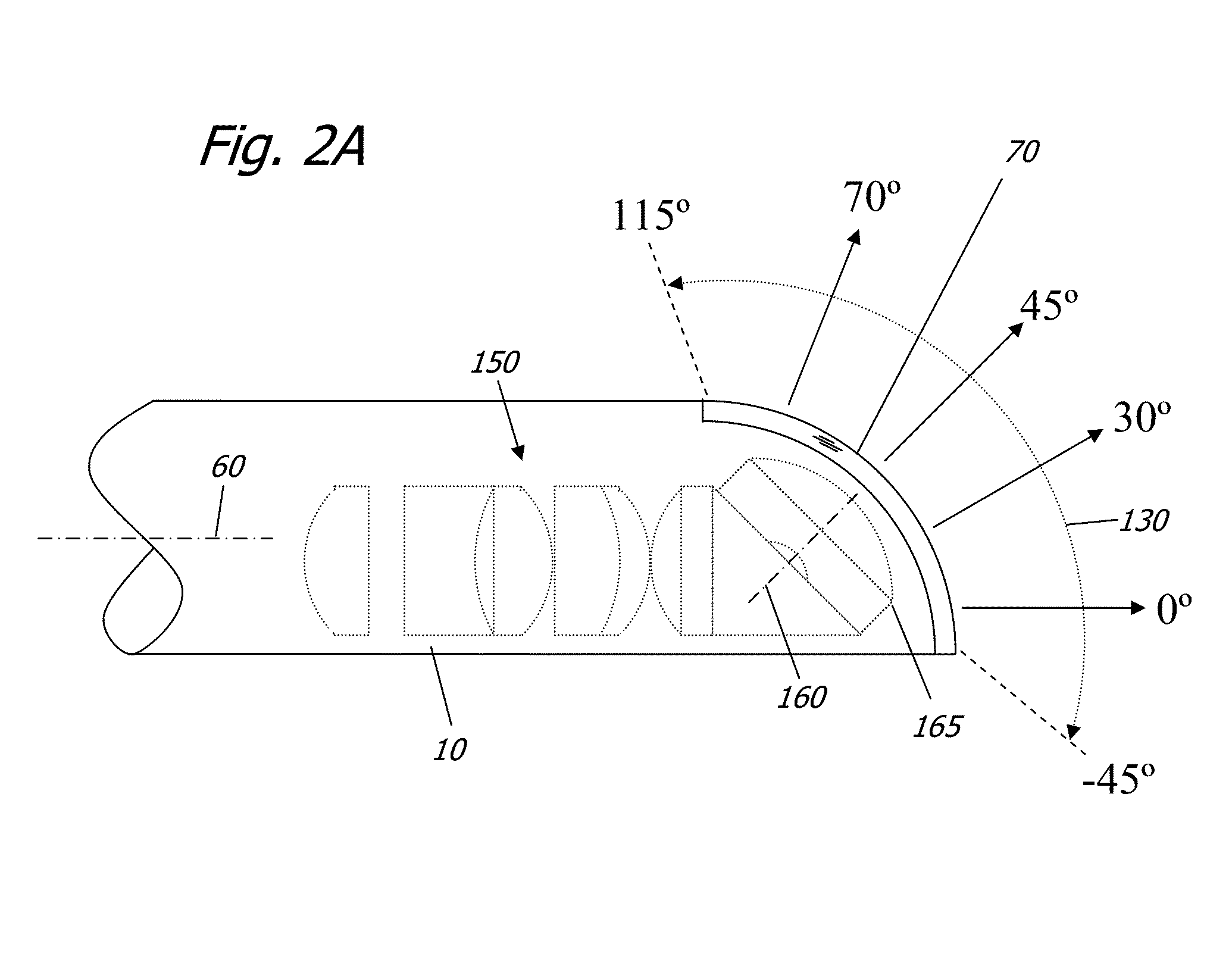
[0058]FIGS. 2A and 2B depict a preferred embodiment of the present invention. FIG. 2A depicts a distal tip 10 of an endoscope with a longitudinal axis 60, a viewing window 70, a wide angle lens system 165 with optical center 160 and a transmission system 150. The optical center 160 is angularly offset from the longitudinal axis 60 of the endoscope 10 and covers a viewing range 130 of 160 degrees from −45 to +115 degrees relative to the longitudinal axis. From this configuration, the wide angle lens system 165 simultaneously gathers an endoscopic image field 130 that spans t...


PUM


Abstract

An endoscope with a wide angle lens that comprises an optical axis that is angularly offset from a longitudinal axis of the endoscope such that the optical axis resides at an angle greater than zero degrees to the longitudinal axis. The wide angle lens system simultaneously gathers an endoscopic image field, the endoscopic image field at least spanning the longitudinal axis and an angle greater than ninety degrees to the longitudinal axis. The endoscope includes a transmission system with a lens system having f-sin(theta) distortion or substantially f-sin(theta) distortion that distributes the angle of incidence of the light rays gathered from the endoscopic field of view on to the image surface area in order to even out the information density across the surface area of the imager.

Description

FIELD OF THE INVENTION[0001]The present invention relates to variable direction of view endoscopes, in particular, variable direction of view endoscopes incorporating solid state imagers and wide-angle lens systems. The present invention includes incorporating a lens capable of f-sin(theta) distortion or substantially f-sin(theta) distortion within the transmission system of an endoscope.BACKGROUND OF THE INVENTION[0002]Variable direction of view endoscopes allow a user to change the endoscopic viewing direction without having to change the position of the endoscope itself. Such endoscopes are useful when a user wants to see structures which are beside or behind the tip of the endoscope but cannot easily move the endoscope shaft because of anatomical constraints or constraints imposed by other surgical instruments in the operative field.[0003]Variable direction endoscopy is desirable because it affords surgeons greater flexibility in their procedural approach. Increased viewing mobi...

Claims


Application Information

Patent Timeline
Patent Type & Authority Patents(United States)
IPC IPC(8): A61B1/04A61B1/00
CPCA61B1/045A61B1/05A61B1/00006A61B1/042A61B5/04525G02B23/243A61B1/00188A61B1/00009A61B1/00039A61B1/0005G02B23/2484A61B1/00183A61B1/00096A61B1/00177A61B1/04A61B1/00179A61B1/00174A61B5/35A61B1/0004
Inventor HALE, ERIC L.HOEG, HANS DAVIDDUCKETT, III, GEORGE E.SCHARA, NATHAN JON
Owner KARL STORZ IMAGING INC
Why Eureka
Try Eureka