
Refueling equipment, and method for refueling an aircraft using said equipment

a technology for refueling equipment and aircraft, which is applied in the direction of packaging goods, liquid bottling, packaging under special atmospheric conditions, etc., can solve the problems of reliability problems, flow penetration of flexible hoses under enslaved, and control and monitoring devices mounted on refueling equipment must be subject to periodic verification

Active Publication Date: 2014-07-01
DESAUTEL
View PDF19 Cites 16 Cited by
  • Summary
  • Abstract
  • Description
  • Claims
  • Application Information

AI Technical Summary

Benefits of technology

The invention allows for the fuel pressure to be measured before it reaches the fuel tank. This information is sent to the control system on the equipment, which adjusts the pressure to keep it within the recommended range. Overall, this technology ensures safe and efficient fuel tank operations.

Problems solved by technology

When it leaves the pipe formed on the chassis of the equipment through rigid hoses, the flow penetrates the flexible hose under enslaved, but not continuously monitored, pressure, which poses a reliability problem.
Furthermore, the control and monitoring devices mounted on the refueling equipment must be subject to periodic verification, because they alone set the pressure of the fuel entering the aircraft's fuel tank.
This gauge is not very accessible and the detection of an overpressure depends on the operator's concentration.
Furthermore, even if he detects an overpressure, the operator, who then stays near the fuel tank of the aircraft, cannot act on the flow to decrease its pressure.

Method used


Image

  • Refueling equipment, and method for refueling an aircraft using said equipment
  • Refueling equipment, and method for refueling an aircraft using said equipment
  • Refueling equipment, and method for refueling an aircraft using said equipment

Examples


Embodiment Construction

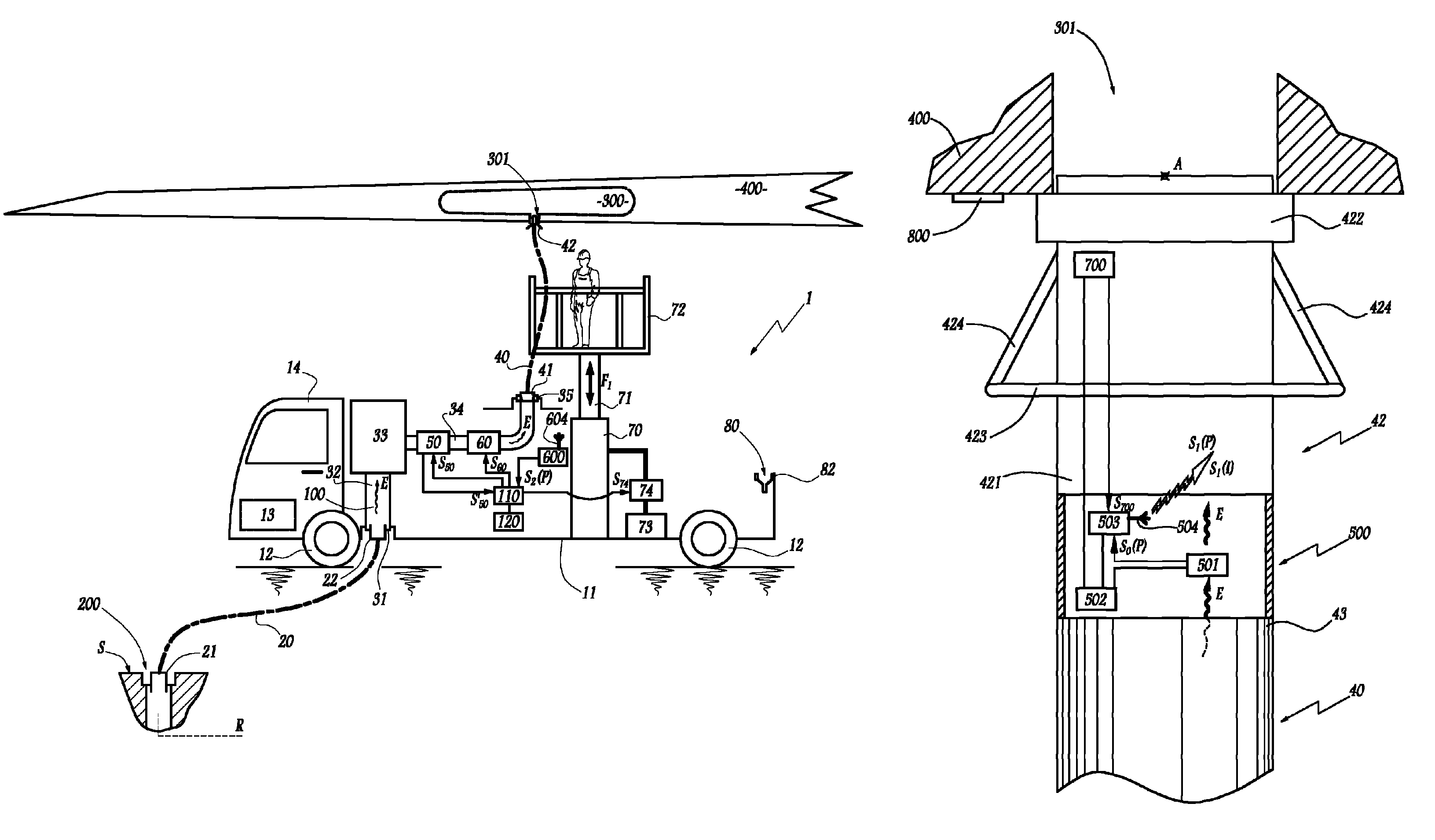
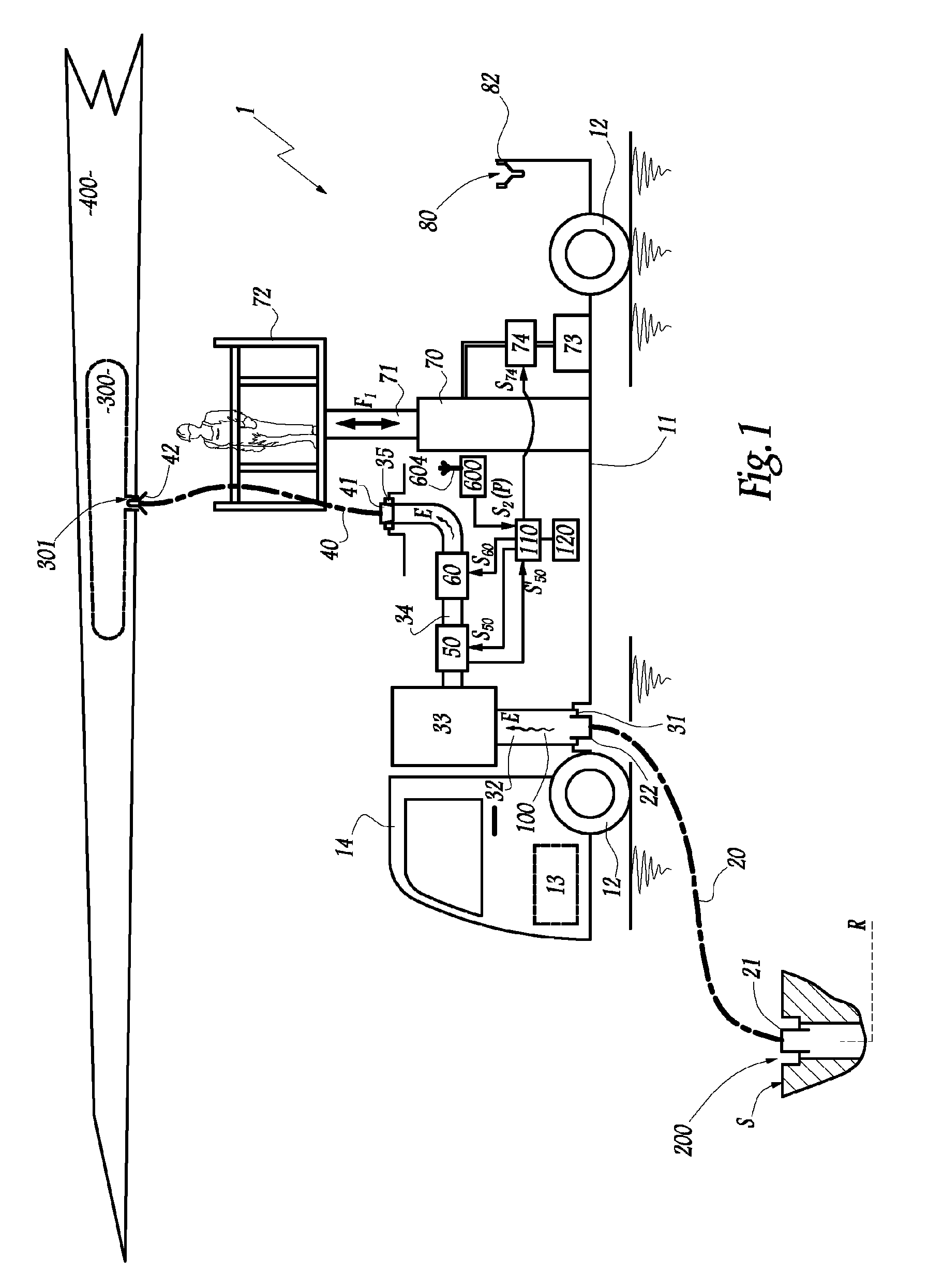
[0033]The refueling equipment or servicer 1 shown in FIG. 1 generally assumes the form of an industrial vehicle and includes a chassis 11 that rests on the ground via wheels, two of which are visible with reference 12, and which supports an internal combustion engine 13 above which a cab 14 is positioned for the equipment's driver.

[0034]The equipment 1 is equipped with a flexible hose 20 making it possible to connect it onto an outlet mouth 200 belonging to a fixed fuel distribution grid R in an airport. The mouth 200 is positioned under the surface S of the ground, in the vicinity of a parking space for an aircraft. The hose 20 is equipped with a connector 21 for connecting onto the mouth 200. At its end opposite the connector 21, the hose 20 is equipped with another connector 22 for connecting onto a connector 31 making up the nozzle of a fixed pipe 32 of the equipment 1. In other words, the hose 20 makes it possible to connect the outlet mouth 200 that belongs to the fixed grid R...


PUM


Abstract

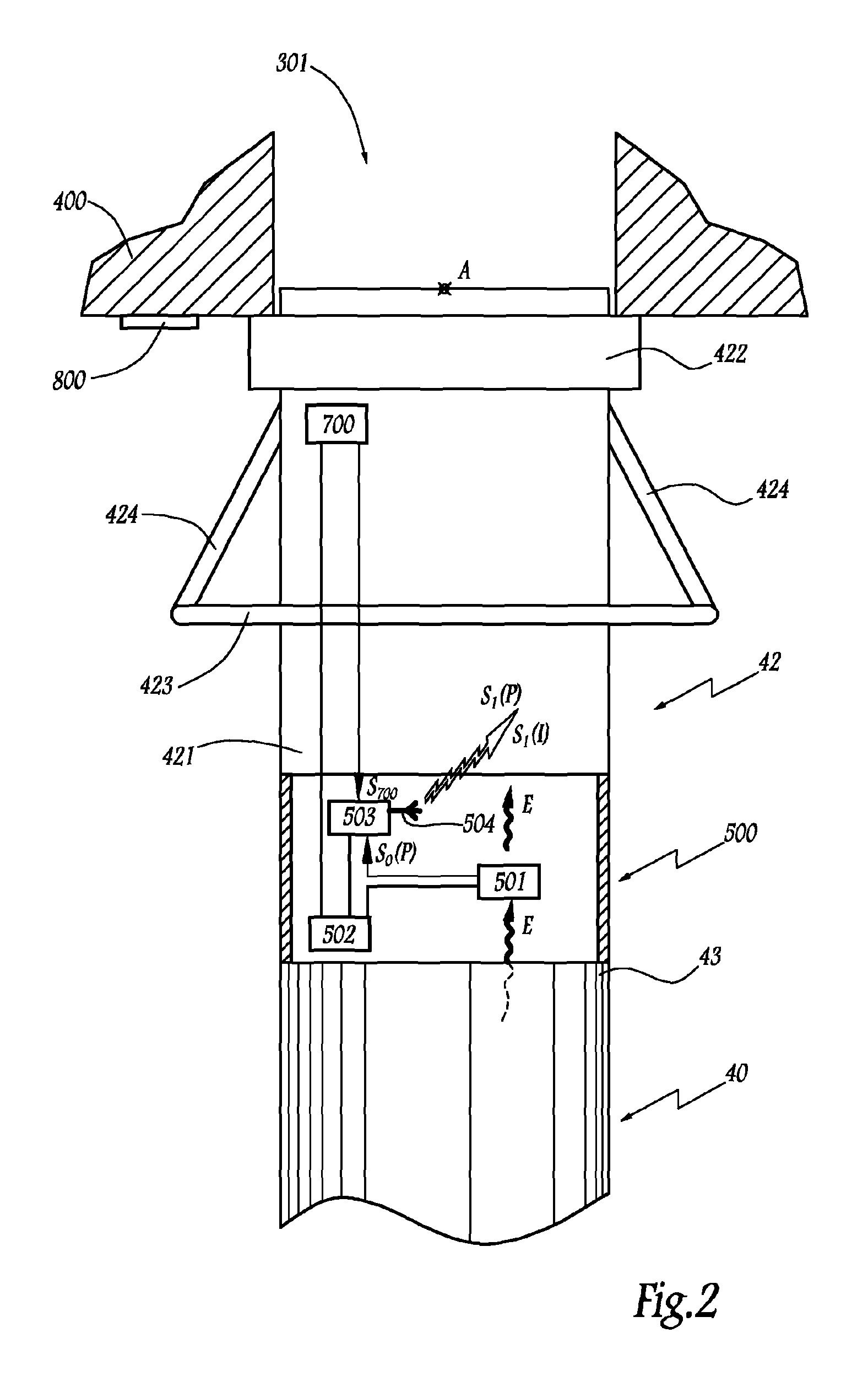
The invention relates to equipment for refueling an aircraft, including a pipe (40) provided with means (42) for connecting onto an intake port (301) of the fuel tank of the aircraft (400) and, at or in the vicinity of the connection means (42), means (501) for determining the value of at least one parameter representative of a flow (E) of fuel passing through the connection means. Said equipment further includes at least one receiver onboard the refueling equipment (1), means (503, 504) for transmitting, to the receiver, a signal (Si(P)) representative of a parameter value predetermined by determination means (501) and an electronic unit capable of receiving, from the receiver, a signal representative of the parameter and of driving at least one flow control and monitoring device in accordance with the signal received from the receiver. The refueling method includes the steps of during a refueling operation, determining the value of at least one parameter representative of the flow (E) at or in the vicinity of the connection means (42), transmitting, to at least one receiver onboard the refueling apparatus, a signal (Si(P)) representative of a parameter value predetermined during the previous step, and automatically driving, in accordance with the signal received by the receiver, a flow control and monitoring device.

Description

BACKGROUND OF THE INVENTION[0001]1. Field of the Invention[0002]The invention relates to a refueling equipment for refueling an aircraft as well as a method for refueling an aircraft using such equipment.[0003]2. Brief Description of the Related Art[0004]At civil and military airports and aerodromes, it is known to use refueling equipments that are moved near the aircrafts to fill their tanks with fuel. A first type of refueling equipment comprises “refueling tankers” which are vehicles provided with a tank from which fuel is drawn to be transferred to a fuel tank of an aircraft. A second type of refueling equipment comprises vehicles intended to connect to an outlet mouth of a fixed fuel distribution grid, sometimes called “hydrant system.” These vehicles of the second type are commonly called “servicers” and are provided to be connected, on the one hand, onto the hydrant system, and on the other hand, onto the fuel tank of the aircraft, while allowing the hydrant system and that f...

Claims


Application Information

Patent Timeline
IPC IPC(8): B64D37/14
CPCB64F1/28
Inventor BECK, CLAUDE
Owner DESAUTEL
Learn More