Thermal generator using magnetocaloric material

a technology of magnetocaloric material and thermal generator, which is applied in the direction of energy-saving heating/cooling, machines using electric/magnetic effects, and machine operation modes, etc. it can solve the problems of reducing the performance of such a thermal generator, which is bound to this temperature gradient, and its limitations in effective heat capacity and thermal efficiency, so as to achieve the effect of improving thermal efficiency

Active Publication Date: 2014-07-08
FRANCE BREVETS SAS
View PDF23 Cites 57 Cited by
  • Summary
  • Abstract
  • Description
  • Claims
  • Application Information

AI Technical Summary

Problems solved by technology

We also know its limitations in effective heat capacity and thermal efficiency.
The result is that the performance of such a thermal generator, which is bound to this temperature gradient, is reduced.

Method used


Image

  • Thermal generator using magnetocaloric material
  • Thermal generator using magnetocaloric material
  • Thermal generator using magnetocaloric material

Examples


first embodiment

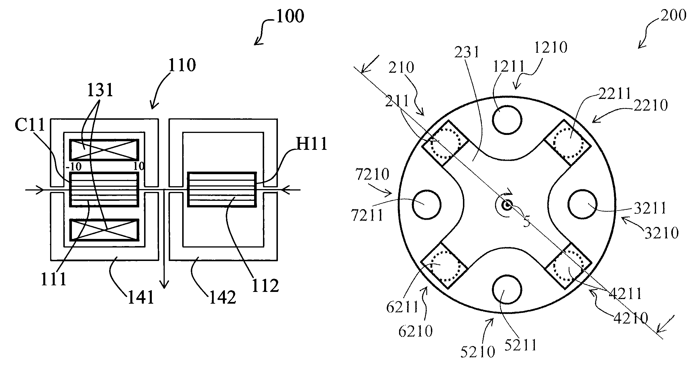
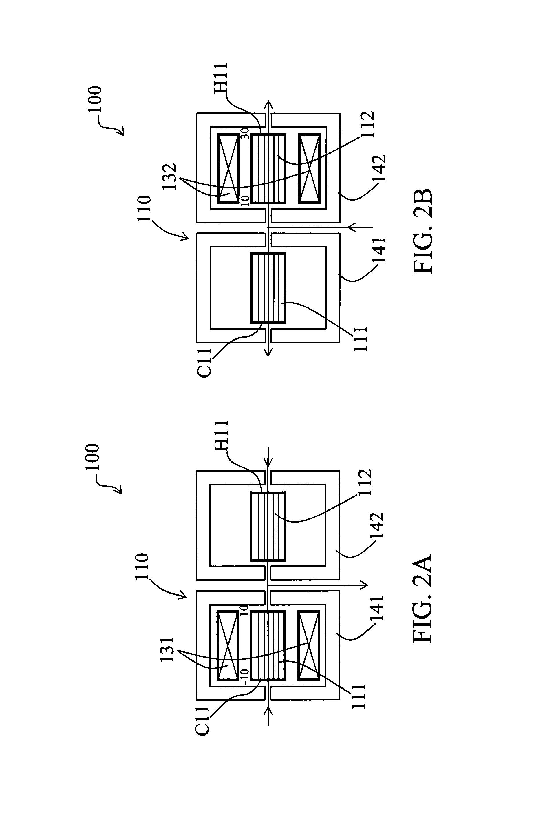
[0031]FIGS. 2A and 2B show, in schematic view, a thermal module 110 of a thermal generator 100 according to the present invention. This thermal module 110 comprises two magnetocaloric elements 111 and 112. The cold end C11 of the thermal module 110 is the end on the left side of FIGS. 2A and 2B of the first magnetocaloric element 111 and the hot end H11 of the thermal module 110 is the end on the right side of FIGS. 2A and 2B of the second magnetocaloric element 112. Each magnetocaloric element 111 and 112 is subjected to a magnetic cycle realized by one corresponding magnetic assembly 131, 132. During a first alternation (see FIG. 2A), the heat transfer fluid F flows from the cold end C11 of the magnetocaloric element 111 subjected to an increase of the magnetic field to the other end of this magnetocaloric element 111 (its hot end) and from the hot end H11 of the magnetocaloric element 112 subjected to a decrease of the magnetic field to the other end of this magnetocaloric elemen...

second embodiment

[0034]FIGS. 3A and 3B show, in schematic view, a thermal module 210 of a thermal generator 200 according to the present invention. This example is particularly adapted for rotational thermal generators 200 where the magnetic assemblies 231, 232, 233 are fixed to a shaft in rotation around the longitudinal axis 5 of the generator 200. FIGS. 4A and 4B represent a simplified front view of this thermal generator 200 showing more particularly one part of a magnetic assembly 231 in the positions corresponding respectively to these of FIGS. 3A and 3B.

[0035]FIGS. 4A, 4B, 4C and 4D show the interaction between the magnetic assemblies 231 and one magnetocaloric element 211, 1211, 2211, 3211, 4211, 5211, 6211 and 7211 of the eight thermal modules 210, 1210, 2210, 3210, 4210, 5210, 6210 and 7210 of this thermal generator 200. Each magnetic assembly 231, 232, 233 is constituted by two groups of four permanent magnets facing each other and forming a magnetic gap 6 in which the magnetocaloric mate...


PUM


Abstract

A thermal generator (100) with at least one thermal module (110) comprising at least two magnetocaloric elements (111, 112). The thermal generator is characterized in that it comprises at least two magnetic assemblies (131, 132) in which one magnetic assembly (131, 132) subjects at least one magnetocaloric element (111, 112) of the thermal module (110) to alternate magnetic phases. The thermal generator is further characterized in that it comprises a thermally insulating body insulating the magnetic assemblies (131, 132) from each other and forming thermally insulated cells (141, 142) comprising one magnetic assembly (131, 132) and its corresponding magnetocaloric elements (111, 112).

Description

TECHNICAL FIELD[0001]The present invention concerns a thermal generator with at least one thermal module comprising at least two magnetocaloric elements.BACKGROUND OF THE INVENTION[0002]The technology of magnetic refrigeration at room temperature is known for more than twenty years and we know its advantages in terms of ecology and sustainable development. We also know its limitations in effective heat capacity and thermal efficiency. Therefore, research in this field tends to improve the performance of such a generator by acting on various parameters like the strength of the magnetic field, the performances of the magnetocaloric materials, the heat exchange surface between the heat transfer fluid and the magnetocaloric materials, the performance of the heat exchangers, etc.[0003]The choice of the magnetocaloric materials is a determining factor and has a direct impact on the performances of a magnetocaloric thermal generator. The magnetocaloric effect reaches a peak around the Curi...

Claims


Application Information

Patent Timeline
Patent Type & Authority Patents(United States)
IPC IPC(8): F25B21/00F25B21/02
CPCF25B21/00F25B2321/002Y02B30/66Y02B30/00
Inventor HEITZLER, JEAN-CLAUDEMULLER, CHRISTIAN
Owner FRANCE BREVETS SAS
Why Eureka
Try Eureka