Dual magnetic phase stator laminations for stator permanent magnet electric machines

a permanent magnet electric machine and magnetic phase technology, applied in the field of electric machines, can solve the problems of reducing affecting so as to achieve the effect of increasing the power capability of the machin

Inactive Publication Date: 2014-08-28
GENERAL ELECTRIC CO
View PDF8 Cites 17 Cited by
  • Summary
  • Abstract
  • Description
  • Claims
  • Application Information

AI Technical Summary

Benefits of technology

[0007]Therefore, it would be desirable to provide stator laminations for a stator permanent magnet machine that can be formed via a single cutting operation, while minimizing the permanent magnet flux leakage typically associated with laminations formed from a single material so as to increase the machine's power capability.

Problems solved by technology

While the bridges found in typical stator laminations of a stator permanent magnet machine provide the mechanical robustness necessary for the laminations to be easily formed (such as in a single cutting operation), the bridges also can have a negative impact on the machine's power capability.
That is, as the bridges are formed of the same soft, magnetic material as the rest of the stator lamination, the bridges form a leakage path for the permanent magnet flux, thereby reducing the machine's power capability.
Furthermore, as the magnetic bridges of the stator laminations need to be thick in order to provide sufficient mechanical strength to the lamination, this thickness of the bridges provides a larger leakage path for the permanent magnet flux, so as to further reduce the machine's power capability.

Method used


Image

  • Dual magnetic phase stator laminations for stator permanent magnet electric machines
  • Dual magnetic phase stator laminations for stator permanent magnet electric machines
  • Dual magnetic phase stator laminations for stator permanent magnet electric machines

Examples


Embodiment Construction

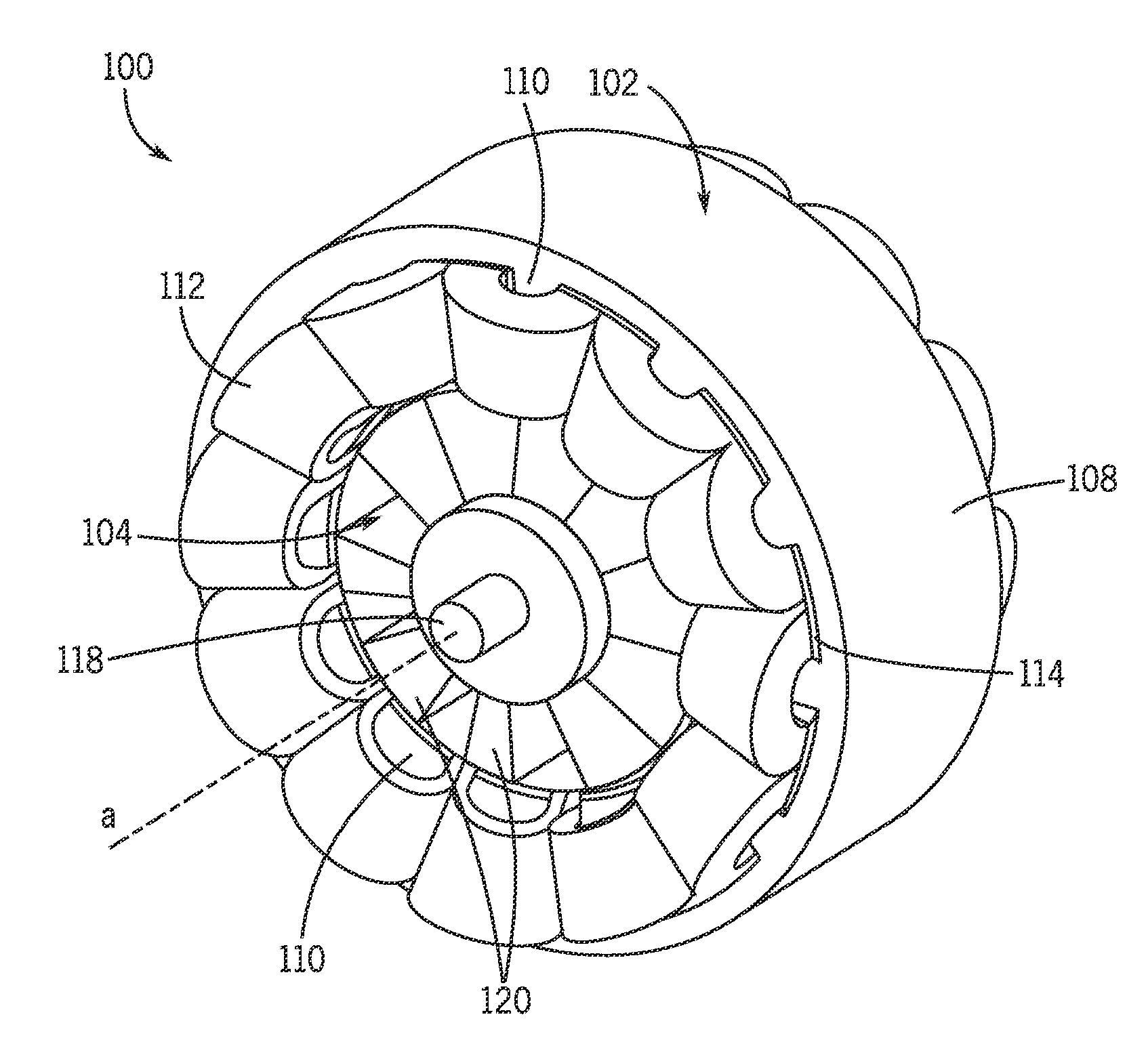
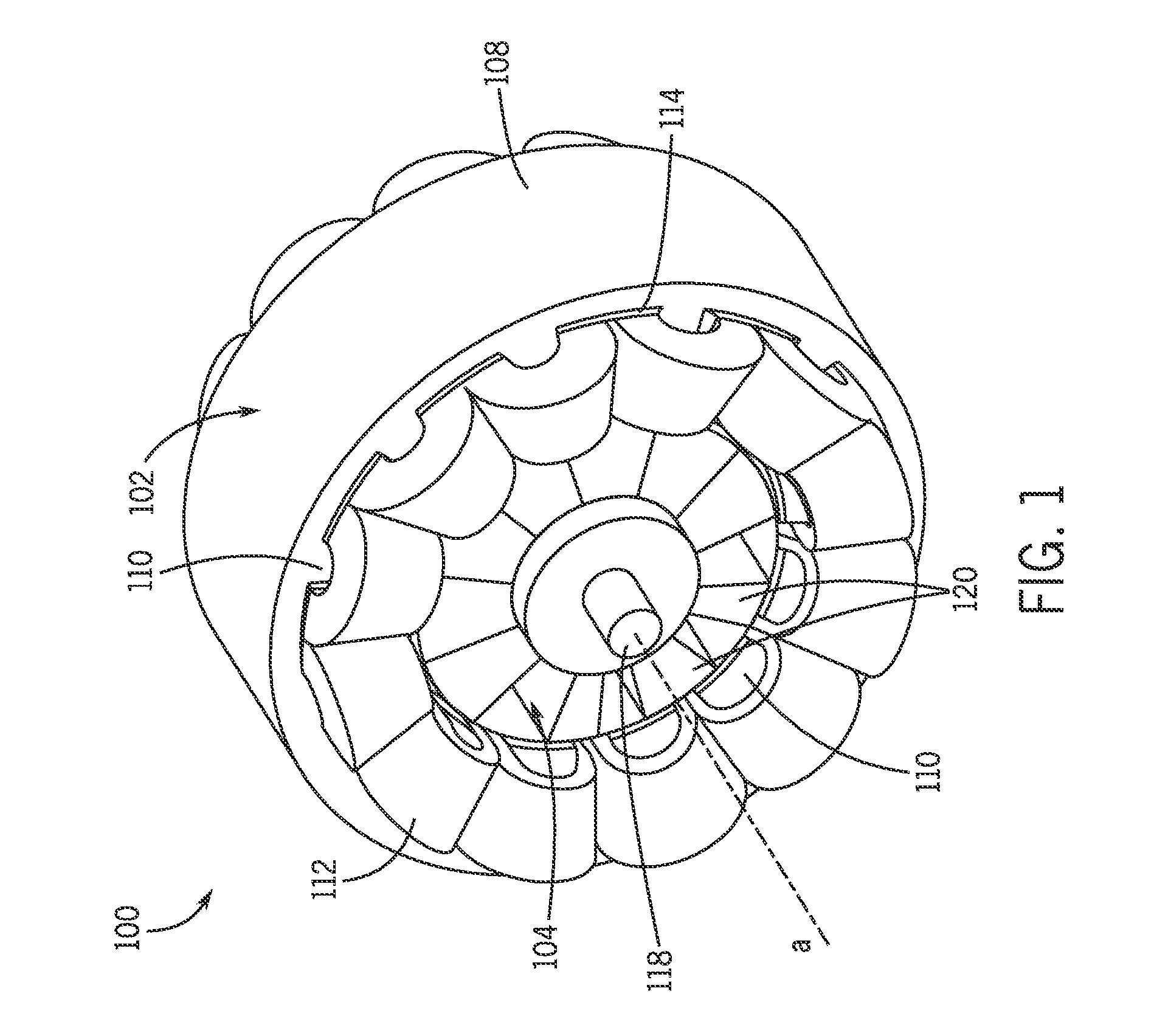
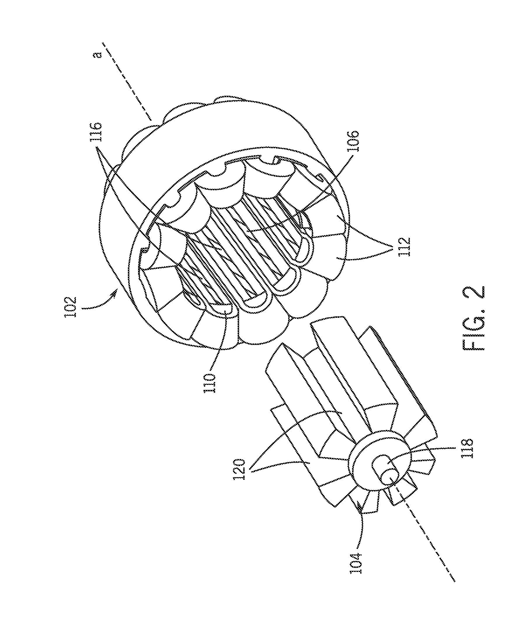
[0031]Referring to FIGS. 1 and 2, therein are shown views of a portion of a stator permanent magnet machine 100 (such as an electric motor or generator). The stator permanent magnet machine 100 can include a substantially concentrically disposed stator 102 and rotor 104. For example, the stator 102 can define a stator bore 106 within which the rotor 104 can be disposed. The stator bore 106 and the rotor 104 may be substantially cylindrical, and may be elongated so as to define an axis a. The rotor 104 can be coupled to a shaft 118 that is configured to rotate about the axis a.

[0032]The stator section may include an outer casing 108 (sometimes referred to as the “back iron” or “yoke”), and one or more teeth 110 each extending, say, radially inward from the outer casing. Conductive windings 112 can be wound around respective teeth 110. Insulation 114 can be included so as to provide electrical isolation between the outer casing 108 / teeth 110 and the conductive windings 112. The stator...


PUM

PropertyMeasurementUnit
areaaaaaaaaaaa
coefficient of thermal expansionaaaaaaaaaa
mechanical stabilityaaaaaaaaaa

Abstract

A dual magnetic phase stator lamination for use in stator permanent magnet electric machines is disclosed. The permanent magnet electrical machine includes a rotor mounted for rotation about a central axis and a stator positioned about the rotor and comprising a plurality of stator laminations, wherein each of the stator laminations is composed of a dual magnetic phase material and includes a first stator lamination portion comprising a magnetic material and a second stator lamination portion comprising a non-magnetic material, the second stator lamination portion comprising an area positioned adjacent to each of a plurality of permanent magnets embedded in the stator lamination. The second stator lamination portion comprises a heat treated portion of the stator lamination, with the heat treating of the second stator lamination portion rendering the dual magnetic phase material of the stator lamination non-magnetic at the locations of the second stator lamination portion.

Description

GOVERNMENT LICENSE RIGHTS[0001]This invention was made with Government support under contract number DE-EE0005573 awarded by the United States Department of Energy. The Government has certain rights in the invention.BACKGROUND OF THE INVENTION[0002]The invention relates generally to electrical machines and, more particularly, to a dual magnetic phase stator lamination for use in permanent magnet electric machines having the magnets in the stator.[0003]The usage of electrical machines in various industries has continued to become more prevalent in numerous industrial, commercial, and transportation industries over time. In an attempt to realize high performance in electric machines, the choice of using permanent magnet (PM) materials is getting more and more popular for many applications. In such machines, the PMs can either replace electromagnets in traditional designs, or novel topologies can be developed to make the best use of the properties and characteristics of PMs.[0004]One P...

Claims


Application Information

Patent Timeline
Patent Type & Authority Applications(United States)
IPC IPC(8): H02K1/17H02K15/03
CPCH02K1/17H02K15/03H02K1/2773Y10T29/49009
Inventor RAMINOSOA, TSARAFIDYEL-REFAIE, AYMAN MOHAMED FAWZIALEXANDER, JAMES PELLEGRINO
Owner GENERAL ELECTRIC CO
Why Eureka
Try Eureka