Power storage device

a technology of power storage and storage devices, which is applied in the direction of secondary cell details, cell components, electrochemical generators, etc., can solve the problems of reducing the charge-discharge capacity, powdered and peeled material layer, etc., and achieves the effect of reducing the charge-discharge time, improving the charge-discharge efficiency, and reducing the charge-discharge capacity

Active Publication Date: 2012-06-07
SEMICON ENERGY LAB CO LTD
View PDF12 Cites 27 Cited by
  • Summary
  • Abstract
  • Description
  • Claims
  • Application Information

AI Technical Summary

Benefits of technology

[0020]According to one embodiment of the present invention, the charge-discharge efficiency is improved and thus constant voltage (CV) charging becomes unnecessary. Consequently, the charging time is shortened and the cycle characteristics of a negative electrode material can be improved.
[0021]According to one

Problems solved by technology

Therefore, a problem arises in that an active material layer is powdered and peeled from a current collector along with charge and discharge of a battery, for example.
As a countermeasure against this, there is a method in which a surface of

Method used


Image

  • Power storage device
  • Power storage device
  • Power storage device

Examples


embodiment 1

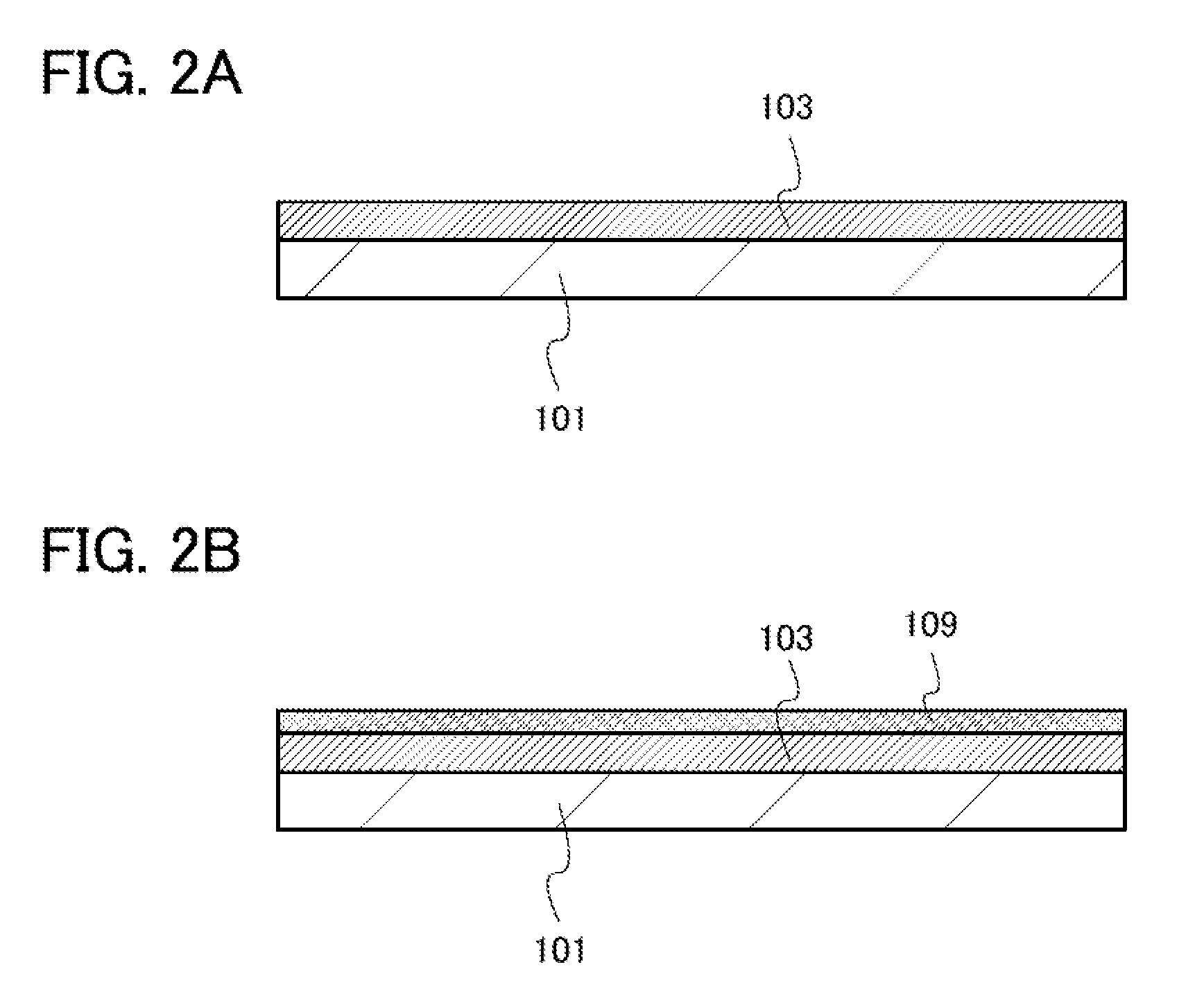
[0034]In this embodiment, an electrode of a power storage device which is one embodiment of the present invention and a method for manufacturing the electrode will be described with reference to FIG. 1 and FIGS. 2A and 2B.

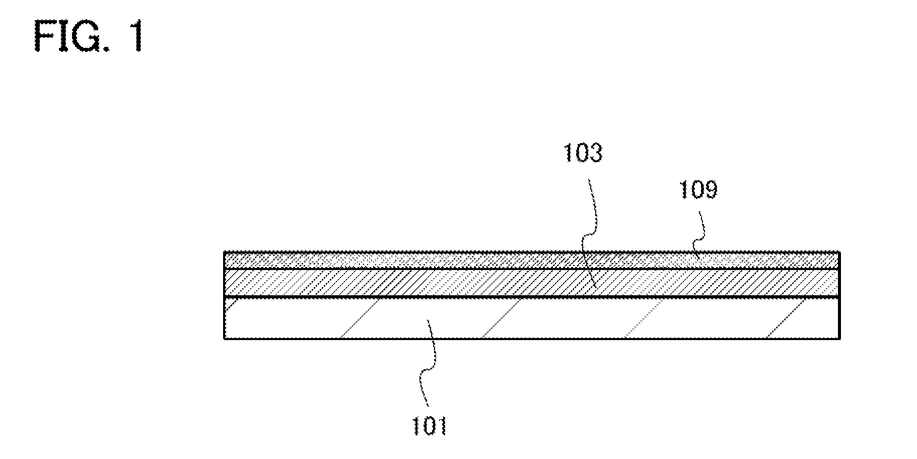
[0035]FIG. 1 illustrates one embodiment of an electrode of a power storage device. The electrode of the power storage device in FIG. 1 includes a current collector 101, an active material layer 103 provided over one surface of the current collector 101, and a layer containing niobium 109 provided over the active material layer 103.

[0036]The current collector 101 is tanned as appropriate using a conductive material which can be used for a negative electrode current collector and has heat resistance high enough to withstand heat treatment to be performed later. Examples of the conductive material which can be used for the current collector include, but are not limited to, copper, platinum, aluminum, nickel, tungsten, molybdenum, titanium, and iron. Note that in the c...

embodiment 2

[0048]In this embodiment, an electrode of a power storage device which is one embodiment of the present invention and a method for manufacturing the electrode will be described with reference to FIG. 3 and FIGS. 4A and 4B.

[0049]FIG. 3 illustrates one embodiment of an electrode of a power storage device. The electrode of the power storage device in FIG. 3 includes a current collector 201, an active material layer 203 provided over one surface of the current collector 201, and a layer containing niobium 209 provided over the active material layer 203. Note that the active material layer 203 includes a crystalline silicon region and a whisker-like crystalline silicon region formed over the crystalline silicon region.

[0050]Next, a method for forming the above electrode will be described with reference to FIGS. 4A and 4B.

[0051]First, as illustrated in FIG. 4A, a crystalline silicon layer is formed as the active material layer 203 over the current collector 201 by an LPCVD method. Deposit...

embodiment 3

[0061]In this embodiment, an electrode of a power storage device which is one embodiment of the present invention and a method for manufacturing the electrode will be described below.

[0062]First, an active material, a conduction auxiliary agent, a binder, and a solvent are mixed to form a slurry. The slurry is prepared in such a manner that the conduction auxiliary agent is dispersed in the solvent containing the binder and then the active material is mixed therein. At this time, in order to improve the dispersion property, it is preferable to reduce the amount of the solvent so that a thick paste is obtained. After that, the solvent is added and the slurry is formed. The proportions of the active material, the conduction auxiliary agent, the binder, and the solvent can be adjusted as appropriate; the higher the proportions of the conduction auxiliary agent and the binder are, the higher the battery performance per the amount of the active material can be.

[0063]As the active materia...


PUM


Abstract

A power storage device which has improved performance such as higher discharge capacity and in which deterioration due to peeling or the like of an active material layer is less likely to be caused is provided. In an electrode for the power storage device, phosphorus-doped amorphous silicon is used for the active material layer over a current collector as a material that can be alloyed with lithium, and niobium oxide is deposited over the active material layer as a layer containing niobium. Accordingly, the capacity of the power storage device can be increased and the cycle characteristics and the charge-discharge efficiency can be improved.

Description

TECHNICAL FIELD[0001]The present invention relates to power storage devices.[0002]Note that the power storage device indicates all elements and devices which have a function of storing power.BACKGROUND ART[0003]In recent years, a variety of power storage devices such as lithium secondary batteries, lithium ion capacitors, and air cells have been developed. In particular, a lithium secondary battery in which charge and discharge are performed by transfer of lithium ions between a positive electrode and a negative electrode has been attracting attention as a secondary battery with high output and high energy density.[0004]An electrode for a power storage device is manufactured by forming an active material layer over one surface of a current collector. The active material layer is formed using an active material such as carbon or silicon, which can store and release ions behaving as carriers. For example, when an active material layer is formed using silicon or phosphorus-doped silico...

Claims


Application Information

Patent Timeline
IPC IPC(8): H01M4/66H01M10/02H01G9/032H01G11/06H01G11/22H01G11/30H01G11/38H01M4/134H01M4/38H01M4/46
CPCH01G11/06H01G11/50H01M4/382Y02E60/122H01M10/0562Y02E60/13H01M4/661Y02E60/10Y02T10/70H01G11/22H01M4/134H01M4/38H01M4/46H01M10/05H01G11/68H01G11/72H01M4/366H01M4/386H01M10/0525H01M2004/027
Inventor KURIKI, KAZUTAKAINOUE, NOBUHIROOGINO, KIYOFUMI
Owner SEMICON ENERGY LAB CO LTD
Why Eureka
Try Eureka