USB power management and load distribution system

a power management and load technology, applied in the direction of power to power outlet, safety/protection circuit, transportation and packaging, etc., can solve the problems of aircrafts with limited power supply, over-demand condition of electrical systems, and electrical systems, and achieve the effect of increasing power capacity setting

Active Publication Date: 2018-03-13
IMAGIK INT CORP
View PDF59 Cites 30 Cited by
  • Summary
  • Abstract
  • Description
  • Claims
  • Application Information

AI Technical Summary

Benefits of technology

[0012]In accordance with a further feature of the present invention, the PMLD circuit is operable to receive an indication of a number of PEDs connected to the at least one PPCO circuit; and the power capability setting is increased as a result of the PMLD circuit determining that the number of PEDs connected to the at least one PPCO circuit was reduced.

Problems solved by technology

In such fixed power supply environment, additional ancillary electrical loads in the aircraft could result in an over-demand condition on the electrical system, i.e., the fixed capacity generators.
However, the problem remains that aircrafts have a limited power supply.
Existing systems in the industry that manage the power available to passenger PEDs deny power to the passenger in some manner, such as, for example, disabling the power supply to passenger PEDs at a certain threshold.
The primary reason why existing systems deny power to some or all passenger PEDs is that such loads on the aircraft's electrical system by, in some cases, a fairly large number of passengers (e.g., the typical Boeing 747-400 aircraft can transport up to 492 passengers) simultaneously demanding power for their PEDs could overwhelm the aircraft's electrical system, resulting in an unsafe condition.
For example, modern PEDs, including laptops, smart devices, and tablets, can draw anywhere from 2.5 W to 100 W. Such power consumption multiplied by hundreds of passengers could overwhelm the aircraft's electrical system in an unsafe manner.
At the same time, denial of power to passenger PEDs, while not necessarily unsafe, is still an undesirable outcome and will likely reduce passenger satisfaction.
Unfortunately, existing power management systems for commercial passenger aircrafts have not been designed to support such high power consuming devices within their fixed power supply environment.

Method used


Image

  • USB power management and load distribution system
  • USB power management and load distribution system
  • USB power management and load distribution system

Examples


Embodiment Construction

[0041]While the specification concludes with claims defining the features of the invention that are regarded as novel, it is believed that the invention will be better understood from a consideration of the following description in conjunction with the drawing figures, in which like reference numerals are carried forward. It is to be understood that the disclosed embodiments are merely exemplary of the invention, which can be embodied in various forms.

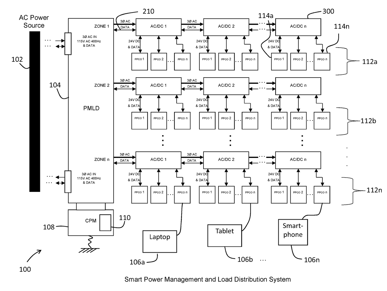
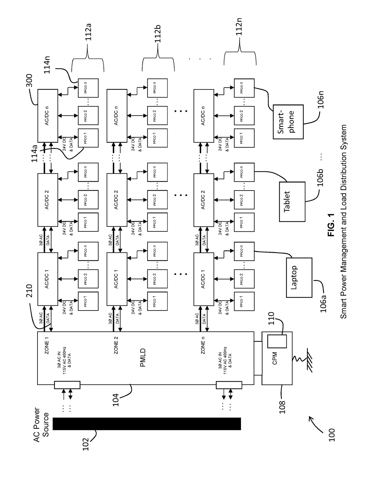
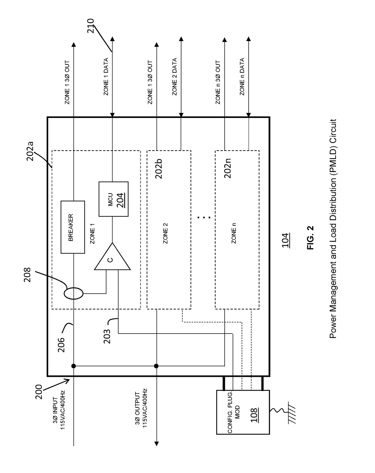
[0042]The present invention provides a novel and efficient power management and load distribution system that dynamically manages power and load distribution. Preferred embodiments of the present invention are configured to efficiently manage power and load distribution for a passenger aircraft, without denying power to passenger PEDs.

[0043]Embodiments of the invention provide a smart power management and load distribution (PMLD) circuit, an AC / DC conversion circuit, and a plurality of USB / USB-PD programmable output capability outlet c...


PUM


Abstract

A power management system includes a power management and load distribution (PMLD) circuit within an airplane coupled to an AC power source, at least one AC / DC conversion circuit operable to convert the AC power into a DC power, and at least one programmable output capability outlet (PPCO) circuit operable to receive the DC power. The PMLD circuit stores a predetermined maximum power limit, continuously measures a power output, and increases or decreases a power capability setting based on a comparison of the measured power output to the predetermined maximum power limit. The PPCO circuit includes a USB connector couplable to a personal electronic device (PED) of a passenger for charging the PED at an amount of DC power indicated by the power capability setting. The PPCO circuit is also operable to negotiate a power contract with the PED.

Description

FIELD OF THE INVENTION[0001]The present invention relates generally to power management and load distribution systems, and, more particularly, relates to a system that manages power distribution from a limited AC power source for charging personal electronic devices.BACKGROUND OF THE INVENTION[0002]Commercial passenger aircraft conventionally include 115V AC, 400 Hz electrical systems to supply power for the operation of on-board electrical loads. The AC power source for aircraft is typically one or more engine-driven generators with a fixed power capacity. In such fixed power supply environment, additional ancillary electrical loads in the aircraft could result in an over-demand condition on the electrical system, i.e., the fixed capacity generators.[0003]With that being said, there is an ever-increasing demand from passengers on commercial passenger aircrafts to power their portable personal electronic devices (“PEDs”), such as, for example, smart phones, tablets, laptops, etc. In...

Claims


Application Information

Patent Timeline
Patent Type & Authority Patents(United States)
IPC IPC(8): B60L1/00B64D47/00H02M7/02H02J7/00
CPCB64D47/00H02M7/02H02J7/0044H02J7/0052H02J2007/0062H02J3/005H02J1/00H02J3/00H02M1/00H02M1/0067H02J7/0013H02J7/0029H02J1/14B60L1/006B60L2200/10B60L2200/18B60L2200/26B64D2221/00H02J7/00036H02J7/00034H02J2310/44B64D11/0015H02J7/00047H02J7/00B64D41/00
Inventor VADILLO, PABLO
Owner IMAGIK INT CORP
Why Eureka
Try Eureka