

Alloy for use in preparation of R-T-B-based sintered magnet and process for preparing R-T-B-based sintered magnet
a technology of rtb-based sintered magnet and alloy, which is applied in the field of alloy for use in the preparation of rtb-based sintered magnet and the process of preparing rtb-based sintered magnet, can solve the problems of reducing the volume fraction of r-rich phase, reducing the quality of r-rich phase, so as to achieve the effect of suppressing the oxidation during the production of sin
- Summary
- Abstract
- Description
- Claims
- Application Information
AI Technical Summary
Benefits of technology
Problems solved by technology
Method used
Image

Examples
example 1
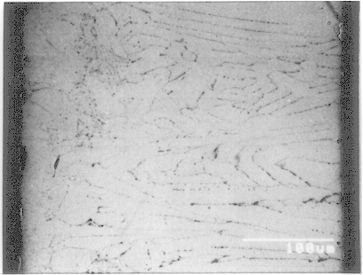
The main-phase alloy having a composition described in Table 1 was melted and then cast by a strip casting method (1450.degree. C. of casting temperature). A roll of made of copper, used in the strip casting had a 40-cm diameter. The circumferential speed of the roll made of copper was 0.98 m / second. The obtained alloy was in the form of flakes and its average thickness was 0.35 mm.
The diffraction electron microscope photograph of the alloy's cross-section by SEM is shown in FIG. 1. A quantitative analysis of the respective phases was carried out by EDX (energy dispersion type X-ray analyzing apparatus). XRD (X-ray diffractometry of powder) was also carried out. From these results, the matrix phase, which appears gray in this photograph, was was the R.sub.2 Fe.sub.14 B phase, and the lamellar phase, which appears in the form of black lines, is the .alpha. Fe phase. Neither the lamellar R-rich phase nor the dendritic .alpha. Fe phase was confirmed. The B-rich phase was confirmed by t...
example 2
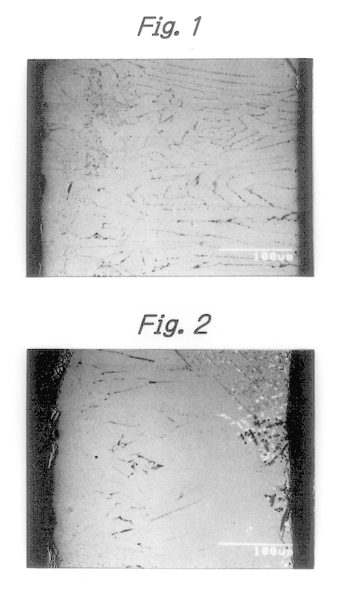
The main-phase alloy having a composition shown in Table 1 was cast by the same strip casting method as in Example 1. The alloy in the form of flakes and having 0.30 mm of average thickness was obtained. The diffraction electron microscope of the alloy's cross-section by SEM was as shown in FIG. 2. A quantitative analysis of the respective phases was carried out by EDX. XRD was also carried out. From these results, the matrix phase, which appears gray in this photograph, is the R.sub.2 Fe.sub.14 B phase; the lamellar phase, which appears in the form of black lines, is the .alpha. Fe phase, the phase in the form of a number of black spots is the dendritic R.sub.2 Fe.sub.17 phase, and a phase, which appears dense black, is the dendritic .alpha. Fe phase. In addition, the R-rich phase appears as white spots in the circumferential portions of the dendritic R.sub.2 Fe.sub.17 phase and the dendritic .alpha. Fe phase. The formation regions of the lamellar .alpha. Fe phase and the dendritic...
example 3
The main-phase alloy having a composition shown in Table 1 was cast by the same strip casting method as in Example 1. The alloy in the form of flakes and having 0.32 mm of average thickness was obtained.
From the SEM diffraction electron image, EDX and XRD of the alloy's cross-section, the following main phases were identified and confirmed: the R.sub.2 Fe.sub.14 B matrix phase; the lamellar .alpha. Fe phase; the dendritic R.sub.2 Fe.sub.17 phase; and the dendritic .alpha. Fe phase. In addition, the R-rich phase appears as a number of spots in the circumferential portions of the dendritic R.sub.2 Fe.sub.17 phase and the dendritic .alpha. Fe phase. The formation of the B-rich phase was confirmed only by XRD but not by the other methods. The formation regions of the lamellar .alpha. Fe phase and the dendritic .alpha. Fe phase were quantitatively obtained by the same method as in Example 1. The results are shown in Table 1.
PUM
| Property | Measurement | Unit |
|---|---|---|
| Thickness | aaaaa | aaaaa |
| Grain size | aaaaa | aaaaa |
| Grain size | aaaaa | aaaaa |
Abstract
Description
Claims
Application Information