Micro CoAxial Cable

Active Publication Date: 2008-02-28
HITACHI METALS LTD
View PDF6 Cites 17 Cited by
  • Summary
  • Abstract
  • Description
  • Claims
  • Application Information

AI Technical Summary

Benefits of technology

[0011]The micro coaxial cable may be more effectively used when it is made with a diameter of 1 mm or less. The insulation layer preferably has a thickness of 0.03 to 0.09 mm, more preferably 0.035 mm to 0.075 mm. The foaming cells provided in the insulation layer preferably have a size of 0.02 to 0.07 mm, and the over-foaming preventing layer preferably has a thickness of 0.01 to 0.04 mm. The over-foaming preventing layer has a lower melt tem

Problems solved by technology

Meanwhile, in the polymer insulation layer in which a region having a foaming cell is crossed with a region having no foaming cell, the dielectric constant may vary locally due to the ‘Skin Effect’, which may cause a fatal ill effect to the transmission characteristics.
However, the micro coaxial cable has a whole diameter of

Method used


Image

  • Micro CoAxial Cable
  • Micro CoAxial Cable
  • Micro CoAxial Cable

Examples


Embodiment Construction

[0020]Hereinafter, preferred embodiments of the present invention will be described in detail with reference to the accompanying drawings for better understanding of the present invention. However, the embodiments of the present invention may be modified in various ways, and the present invention should not be interpreted as being limited to the following embodiments. The embodiments of the present invention are provided just for better understanding of the present invention to those having ordinary skill in the art.

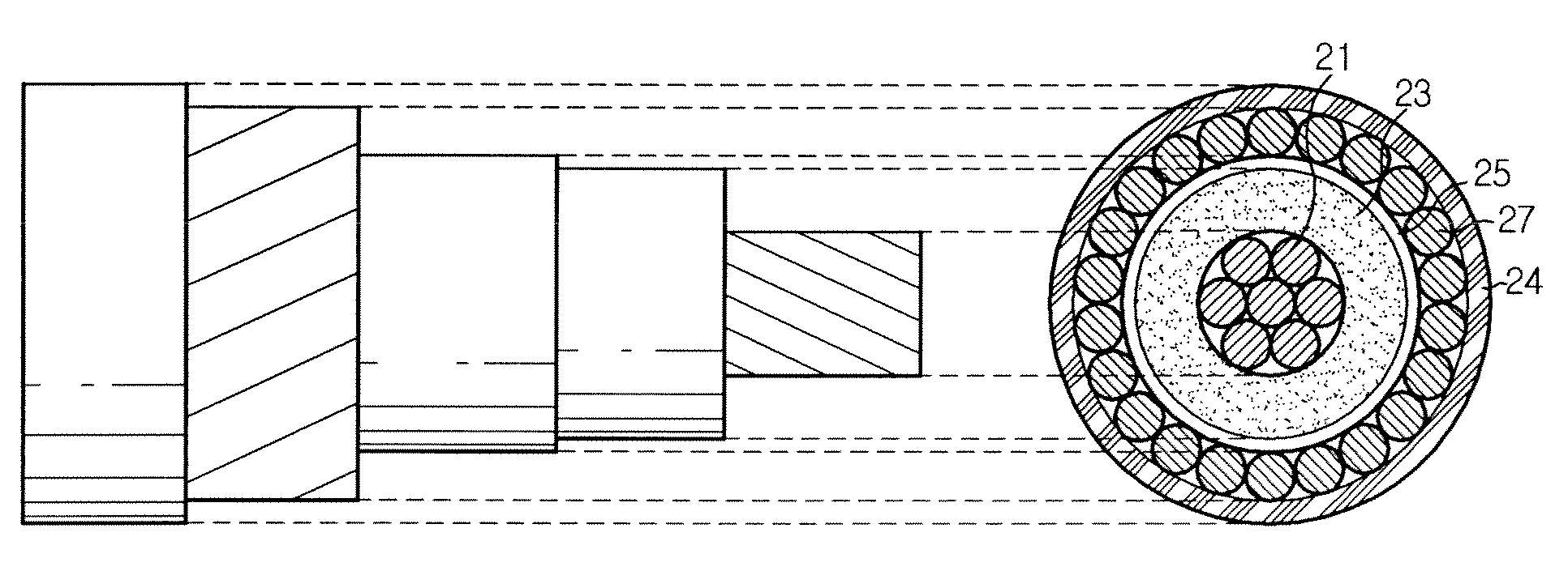
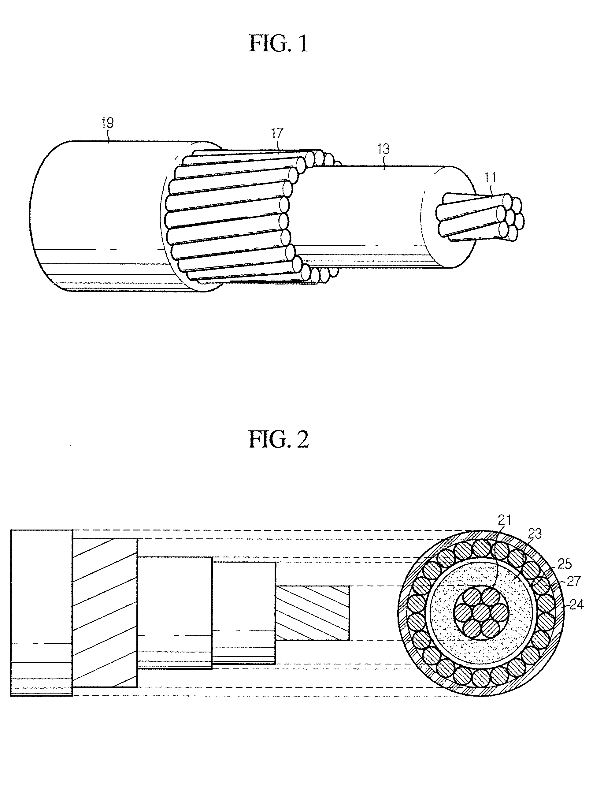
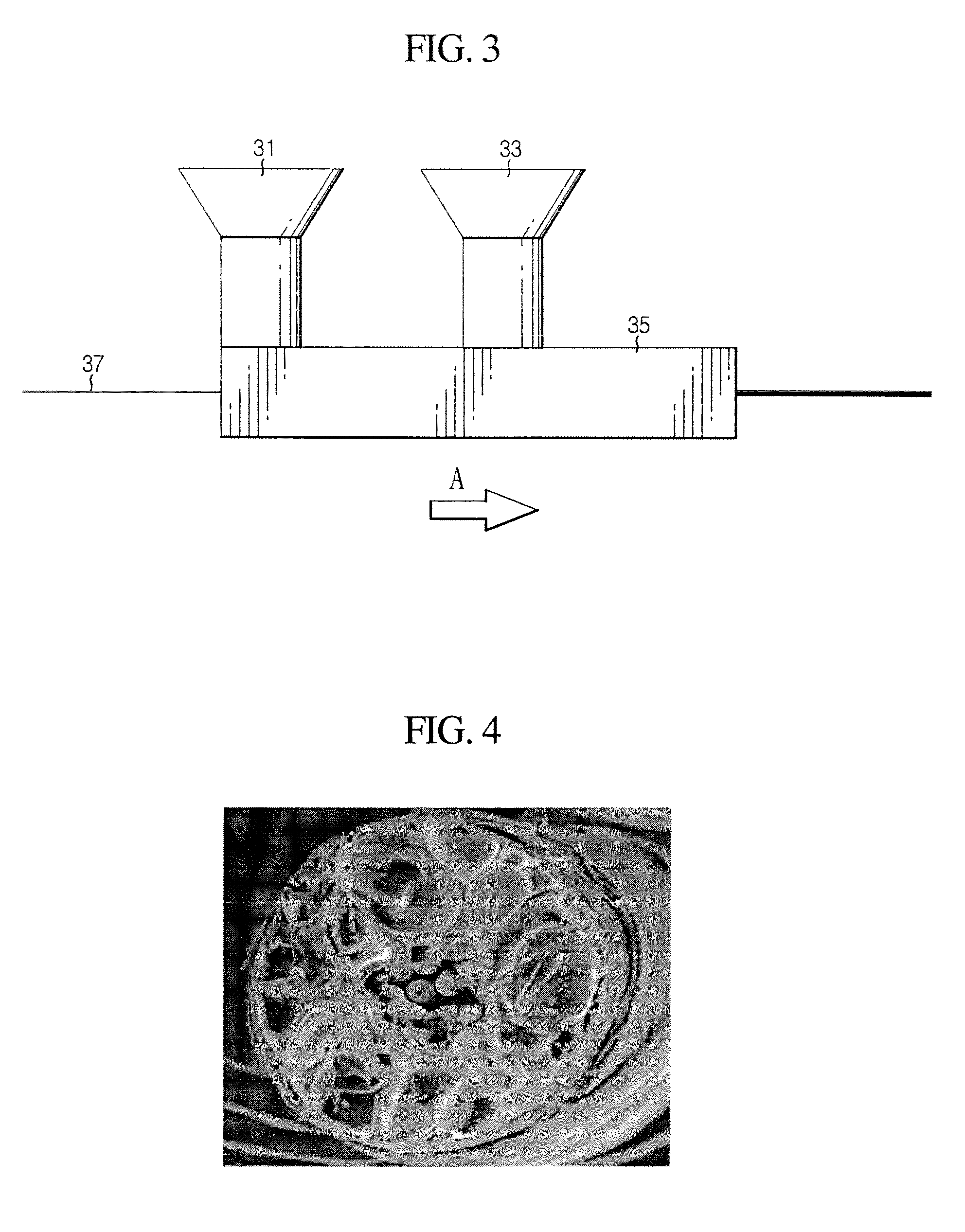
[0021]A micro coaxial cable according to the present invention includes an over-foaming preventing layer formed to surround an insulation layer, so foaming cells formed in the insulation layer are successively adjacently formed with a uniform size. Due to the uniformity of foaming, a dielectric constant in the insulation layer is uniform as a whole without showing any local difference, thereby giving excellent transmission characteristics.

[0022]The micro coaxial cable ac...


PUM


Abstract

A micro coaxial cable includes an inner conductor; an insulation layer having foaming cells and formed to surround the inner conductor; an over-foaming preventing layer formed to surround the insulation layer for the purpose of uniform forming of the foaming cells; a metal shield layer formed to surround the over-foaming preventing layer; and a protective coating layer formed to surround the metal shield layer. The over-foaming preventing layer restrains abnormal growth of foaming cells formed in the insulation layer such that the foaming cells are successively adjacently formed with uniform size. Due to the uniformity of foaming, the dielectric constant of the insulation layer is not locally different but uniform as a whole, thereby capable of improving transmission characteristics. In addition, the micro coaxial cable enables to transmit signals even at a high frequency transmission of GHz range, which was impossible in the prior art.

Description

BACKGROUND OF THE INVENTION[0001]1. Field of the Invention[0002]The present invention relates to a micro coaxial cable, and more particularly to a micro coaxial cable in which foaming cells are formed uniformly in an insulation layer not to show any local difference of dielectric constant in the insulation layer, thereby giving excellent transmission characteristics.[0003]2. Description of the Related Art[0004]A coaxial cable includes a center conductor for transmitting signals, and an outer conductor coaxially formed on the center conductor, and many coaxial cables have been developed in various sizes and various kinds. The coaxial cable is generally used for transmitting signals to CATV or underground antennas. The development of coaxial cables has been mainly directed to a structural design between the center and outer conductors for reducing loss of energy, improvement of dielectric characteristics, and endowment of various schemes to an outside of the outer conductor.[0005]In p...

Claims


Application Information

Patent Timeline
IPC IPC(8): H01B7/17
CPCH01B11/1869H01B11/12H01B11/18H01B11/1839H01B11/1895H01B13/016
Inventor PARK, CHAN-YONGNAM, GI-JOONPARK, JUNG-WONKIM, IN-HAKIM, JUNE-SUNSEO, IL-GUNLEE, GUN-JOO
Owner HITACHI METALS LTD
Why Eureka
Try Eureka