Magnetoresistive material with two metallic magnetic phases

Inactive Publication Date: 2002-04-23
THE RES FOUND OF STATE UNIV OF NEW YORK
View PDF5 Cites 17 Cited by
  • Summary
  • Abstract
  • Description
  • Claims
  • Application Information

AI Technical Summary

Problems solved by technology

However, the nonmagnetic metallic conductor does not contribute to desired scattering of the conduction electrons, and in fact, may act as a low resistance shunt path which decreases the magnetoresistance.
In order to maximize yield, it is undesirable that the secondary electrons hit a surface at a large negative potential.
Ra

Method used


Image

  • Magnetoresistive material with two metallic magnetic phases
  • Magnetoresistive material with two metallic magnetic phases
  • Magnetoresistive material with two metallic magnetic phases

Examples


Embodiment Construction

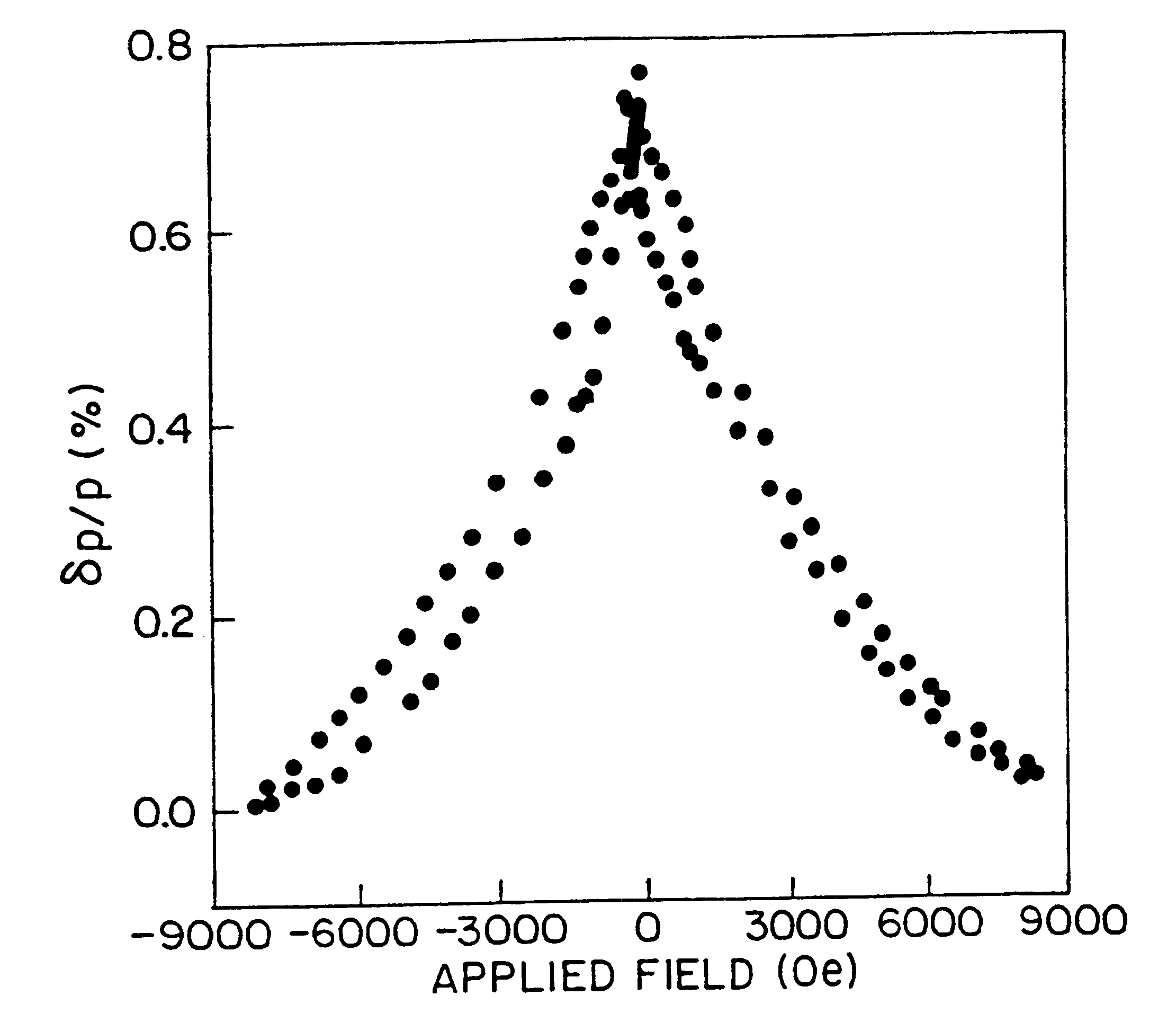
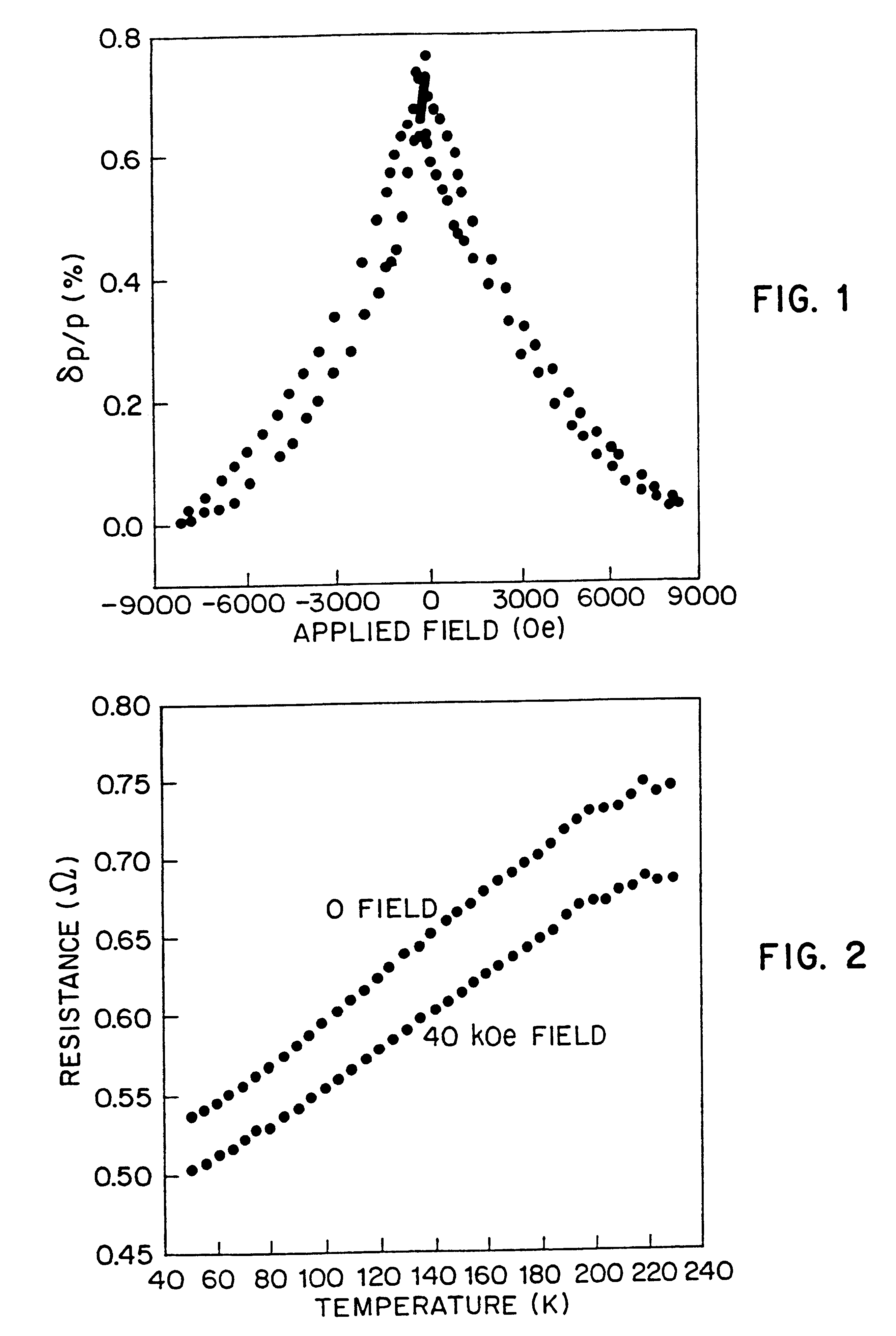
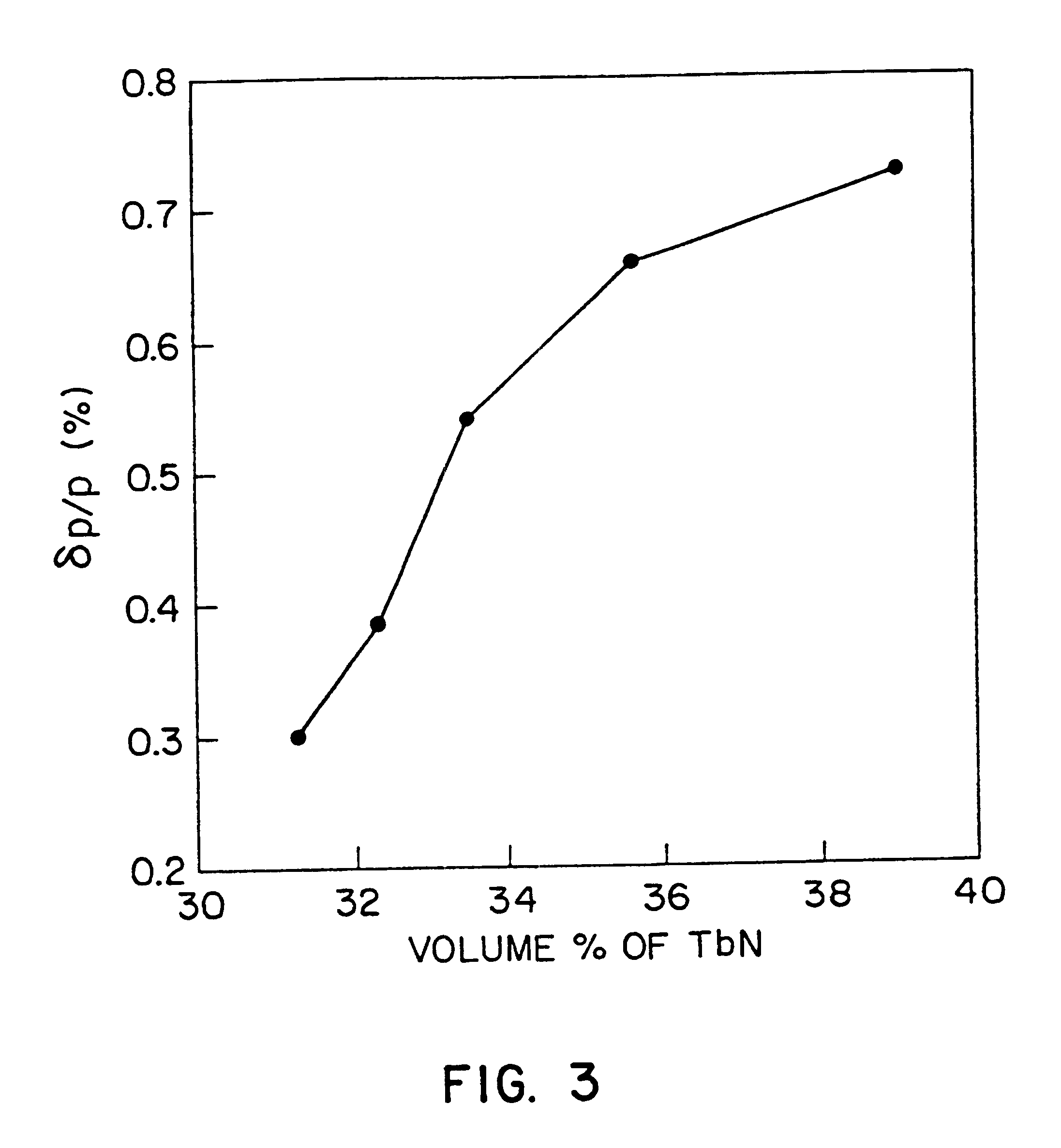
Amorphous Tb.sub.x Co.sub.1-x thin films with the compositions of 25.about.32 atomic % of Tb were prepared using facing target magnetron sputtering with a composite target. The parameter "x" is the atomic fraction of Tb, ranging from 0.25 to 0.32. The film compositions were controlled by changing the Ar sputtering gas pressure (5.about.15 mTorr). In order to induce the phase separation of Co and TbN, nitrogen was introduced into amorphous TbCo thin films by annealing at 650.degree. C. for 12 hours with a continuous flow of 10% H.sub.2 -balance N.sub.2 gas mixture. (Annealing at a lower temperature, such as 400.degree. C., would be possible with a longer dwell time). The pressure of the gas mixture in the annealing furnace was about 1 atmosphere and the gas was flowed at a rate of approximately 500 standard cc / minute. The pressure and flow rate of the gas are not critical control parameters. Phase analysis was made with x-ray diffraction (See FIG. 11) and with secondary electron imag...


PUM


Abstract

A magnetoresistive material with two metallic magnetic phases. The material exhibits the giant magnetoresistance effect (GMR). A first phase of the material includes a matrix of an electrically conductive ferromagnetic transition metal or an alloy thereof. A second precipitate phase exhibits ferromagnetic behavior when precipitated into the matrix and is antiferromagnetically exchange coupled to the first phase. The second precipitate phase can be electrically conductive rare earth pnictide or can be a Heusler alloy. A method of manufacturing magnetoresistive materials according to the present invention employs facing targets magnetron sputtering. The invention also includes a method of detecting magnetic field strength by providing a read head including a portion of one of the magnetoresistive materials according to the invention, exposing the read head to the magnetic field of a magnetic recording medium, sensing electrical resistivity of the portion of material associated with the magnetic field of the magnetic recording medium, and converting the electrical resistivity into a signal which is indicative of the magnetic field strength of the magnetic field associated with the magnetic recording medium. A digital magnetic recording system, according to the present invention, is adapted for use with a magnetic recording medium having a characteristic coercive force and a plurality of stored bits thereon. The bits are stored by magnetic field strength levels of a magnetic field associated with the medium. The system can include a conventional write head and a controller. The system can also include a read head including a portion of magnetoresistive material according to the present invention which is located in proximity to the medium and a suitable resistivity sensor.

Description

1. Field of the InventionThe present invention relates to materials for use in magnetic recording sensors and the like, and more particularly relates to a magnetoresistive material with two metallic magnetic phases.2. Brief Description of the Prior ArtMaterials which exhibit a change in resistance when exposed to a magnetic field are of use in preparing magnetic recording sensors, such as those used, for example, in computer disk drives. At the present time, state-of-the-art computer disk drives employ sensor materials which exhibit the anisotropic magnetoresistance effect (AMR). Materials which exhibit the AMR have a magnetoresistance which depends on how the magnetic field is applied with respect to the direction of current flow.In other types of materials, which exhibit the giant magnetoresistance effect (GMR), a non-magnetic metallic conductor, such as copper, is necessary to create a disordered state of electron spins in a ferromagnet. However, the nonmagnetic metallic conducto...

Claims


Application Information

Patent Timeline
IPC IPC(8): G11B5/00H01F1/00H01F41/18H01F41/14H01F1/03H01F10/00G11B5/008G11B5/012G11B5/39
CPCG11B5/00B82Y25/00H01F1/0302H01F10/007H01F41/183B82Y10/00H01F1/00G11B5/00813G11B5/012G11B2005/3996
Inventor GAMBINO, RICHARD J.KIM, TAEWAN
Owner THE RES FOUND OF STATE UNIV OF NEW YORK
Why Eureka
Try Eureka