Suturing devices and methods for suturing an anatomic valve

a suture device and valve technology, applied in the field of suture devices and methods, can solve the problems of inability to use conventional sutures and suture methods to close an opening, patient risk of infection, delay in recovery, etc., and achieve the effect of increasing pain and reducing recovery

Active Publication Date: 2014-07-08
PANDORA SELECT PARTNERS +6
View PDF107 Cites 47 Cited by
  • Summary
  • Abstract
  • Description
  • Claims
  • Application Information

AI Technical Summary

Benefits of technology

[0009]In some embodiments, a device for suturing an anatomic valve comprises an elongate body, a needle, an arm, and a recess positioned between the elongate body and the arm. The needle can be operatively coupled to the elongate body for movement between a retracted position and an advanced position. The arm can be attached to the elongate body near a distal end of the elongate body for movement between a retracted position and an extended position. The arm can comprise a suture mount that is configured to releasably retain a suture portion. The suture mount can be positioned on the arm such that the needle retrieves the suture portion retained in the suture mount when the needle is moved from the retracted position to the advanced position and returned to the retracted position. The recess can be sized and shaped to receive a leaflet of a valve between the elongate body and the arm without damaging the leaflet.

Problems solved by technology

There are some circumstances under which it is not feasible to use conventional sutures and suturing methods to close an opening.
Additionally, there are some circumstance under which the use of conventional sutures and suturing methods require invasive procedures that subject a patient to risk of infection, delays in recovery, increases in pain, and other complications.
Some heart valves may be weakened or stretched, or may have other structural defects, such as congenital defects, that cause them to close improperly, which can lead to blood flow contrary to the normal flow direction.
Regurgitation causes the heart to work harder to compensate for backflow of blood through these valves, which can lead to enlargement of the heart that reduces cardiac performance.

Method used


Image

  • Suturing devices and methods for suturing an anatomic valve
  • Suturing devices and methods for suturing an anatomic valve
  • Suturing devices and methods for suturing an anatomic valve

Examples


Embodiment Construction

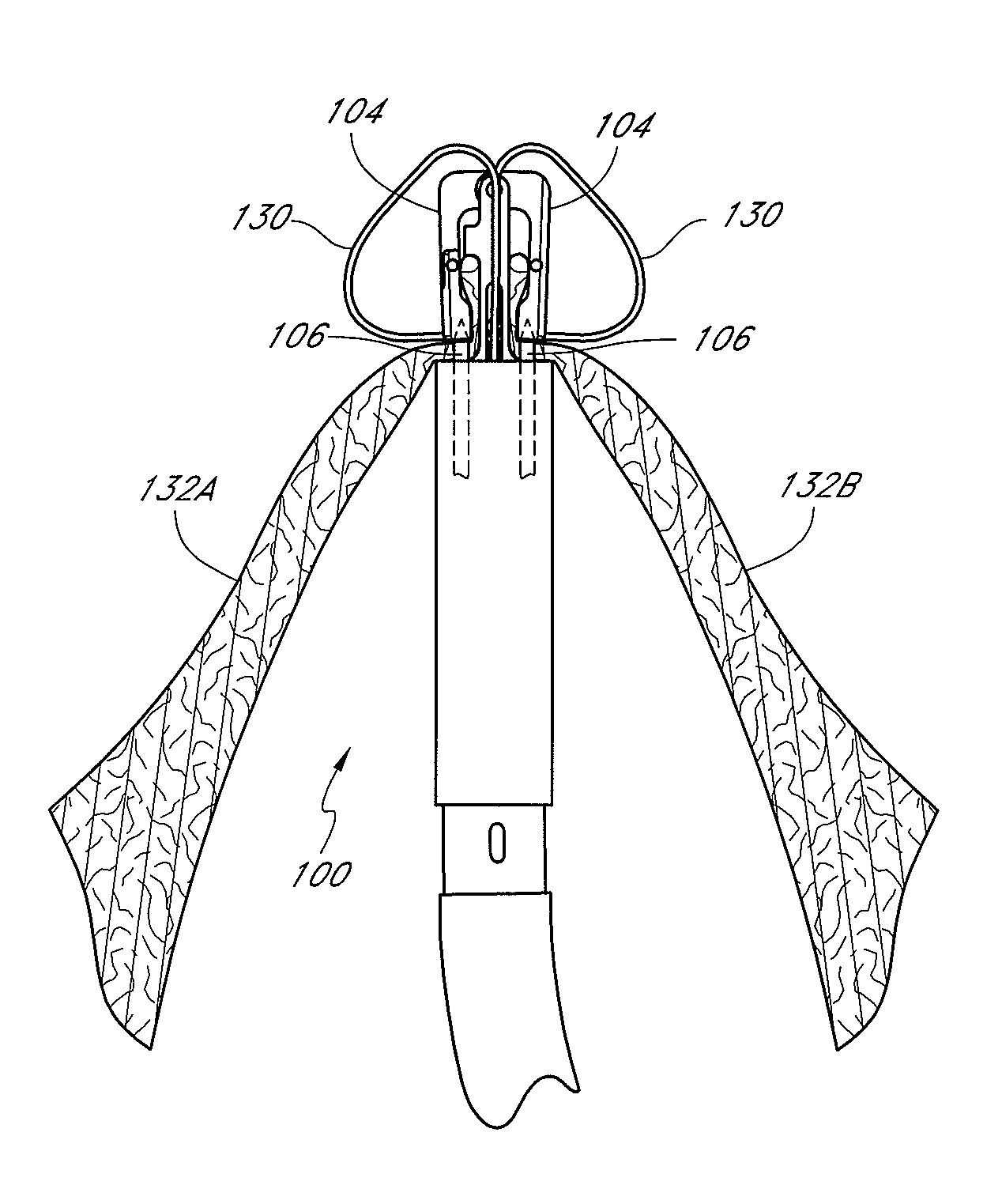
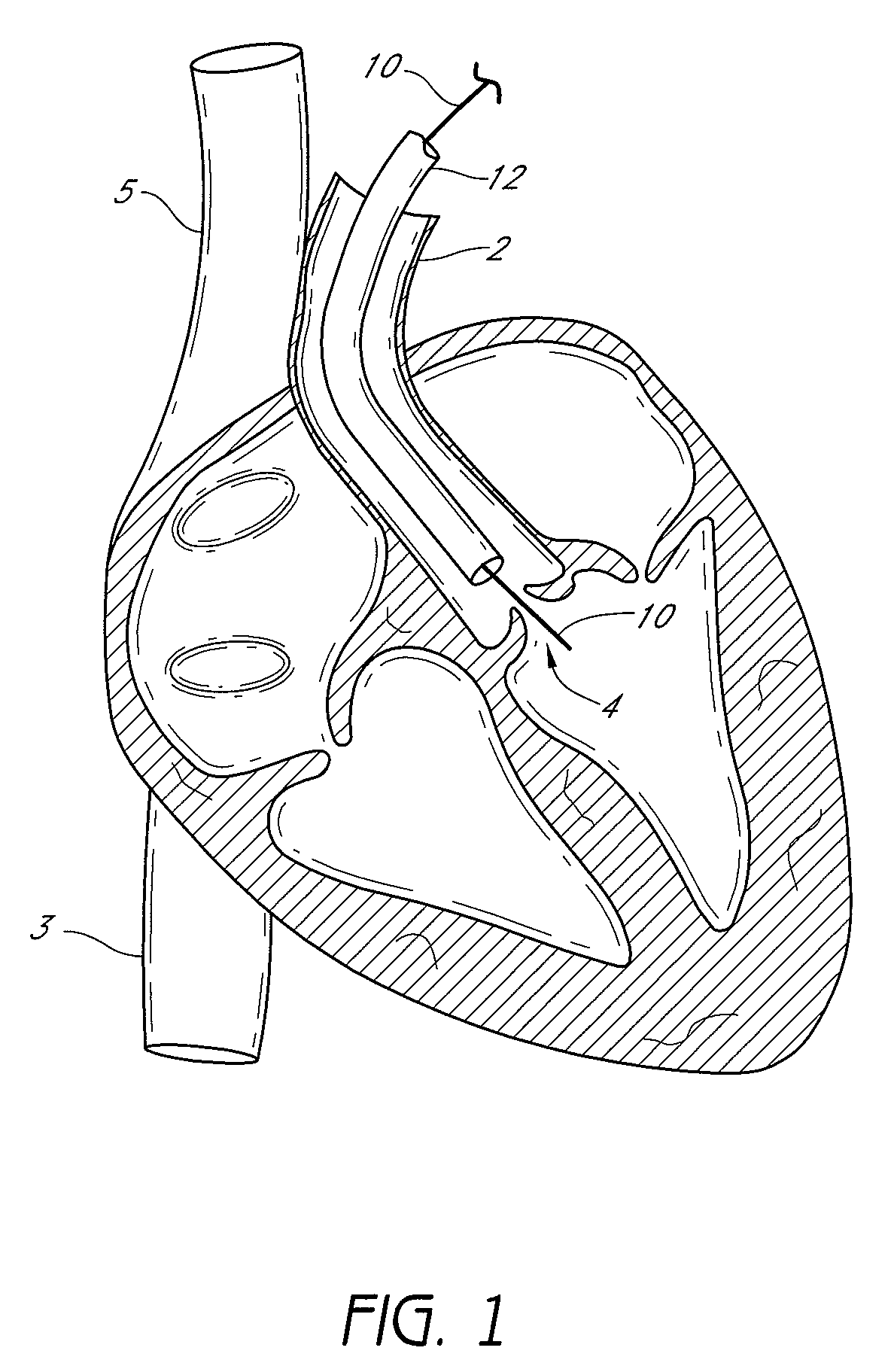
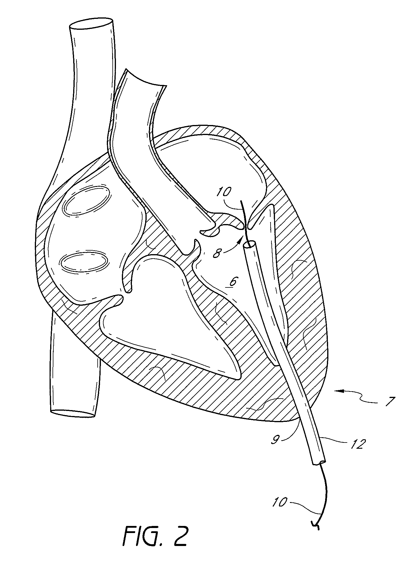
[0060]Embodiments of suturing devices and methods for suturing biological tissue are disclosed herein. The suturing devices and their methods of use can be useful in a variety of procedures, such as treating (e.g., closing) wounds and naturally or surgically created apertures or passageways. For example, the suturing devices can be used to treat an anatomical valve, such as a heart valve, including heart valves that may be weakened or stretched, or have other structural defects, such as congenital defects, that cause them to close improperly. In some embodiments, one or more suturing devices can be used to treat or repair valves, such as the tricuspid, pulmonary, mitral, and aortic valves, for example. In some embodiments, one or more suturing devices can be used to perform procedures such as the Alfieri technique (edge-to-edge repair), replacement of the chordae tendineae, shortening of the chordae tendineae, patch application, leaflet reshaping, and attachment of prosthetics, such...


PUM


Abstract

A device for suturing an anatomic valve has an elongate body, a suture catch mechanism and a suture clasp arm. The suture catch mechanism is operatively coupled to the elongate body for movement between a retracted position and an advanced position. The suture clasp arm is pivotally attached to the elongate body for movement between a retracted position and an extended position. The suture clasp arm has a suture clasp configured to releasably retain a suture portion. In some embodiments, the suture clasp is positioned on the suture clasp arm such that the suture catch mechanism retrieves the suture portion from the suture clasp arm while the arm is at least partially retracted. In some embodiments, the suture clasp arm can be closed about a tissue portion without damaging the tissue portion.

Description

CROSS-REFERENCE TO RELATED APPLICATIONS[0001]This application claims the benefit under 35 U.S.C. §119(e) of U.S. Provisional Application No. 61 / 052,146, filed May 9, 2008, titled SUTURING DEVICE AND METHOD OF SUTURING AN ANATOMIC VALVE, the entire contents of which is hereby incorporated by reference herein and made a part of this specification.TECHNICAL FIELD[0002]Embodiments of the present inventions relate to suturing devices and methods. Some embodiments of the present invention relate to suturing devices and methods for suturing an anatomic valve, for example, a heart valve such as a mitral valve, an aortic valve, a tricuspid valve, or a pulmonary valve.BACKGROUND[0003]Health practitioners frequently use sutures to close various openings such as cuts, punctures, and incisions in various places in the human body. Generally, sutures are convenient to use and function properly to hold openings in biological tissue closed thereby aiding in blood clotting, healing, and prevention of...

Claims


Application Information

Patent Timeline
Patent Type & Authority Patents(United States)
IPC IPC(8): A61B17/04A61B17/12
CPCA61B2017/06042A61B2017/06057A61B2017/0488A61B2017/0472A61B2017/047A61B17/0482A61B17/0469A61B17/04
Inventor NOBLES, ANTHONY A.BROSCH, BENJAMIN G.CREW, JOHN R.
Owner PANDORA SELECT PARTNERS
Why Eureka
Try Eureka