Facet joint fixation system

Inactive Publication Date: 2005-07-07
DEPUY SPINE INC (US)
View PDF52 Cites 212 Cited by
  • Summary
  • Abstract
  • Description
  • Claims
  • Application Information

AI Technical Summary

Benefits of technology

[0009] It is an object of the present invention to provide a facet joint fixation system that provides initial rigidity for stabilizing the face

Problems solved by technology

Accordingly, the threaded portions thereof may be vulnerable under high shear stresses such as those present near the facet joint space.
Accordingly, these devices have the weaknesses discussed above.
In sum, the smooth shaft does not provide the desirable rigidity, while the threaded shaft may be vulnerable under high shear stresses present near the facet joint space.
Moreover, the essentially smooth nature of the pins disclosed in DiCarlo, Clemow an

Method used


Image

  • Facet joint fixation system
  • Facet joint fixation system
  • Facet joint fixation system

Examples


Example

[0034] For the purposes of the present invention, the proximal portion of the shaft represents the proximal third of the shaft, the central portion of the shaft represents the central third of the shaft, and distal portion of the shaft represents the distal third of the shaft. A “fastening surface” is used interchangeably with “a surface adapted for bony fixation”. An “FSU” is a functional spinal unit, including upper and lower vertebrae and an intermediate disc space.

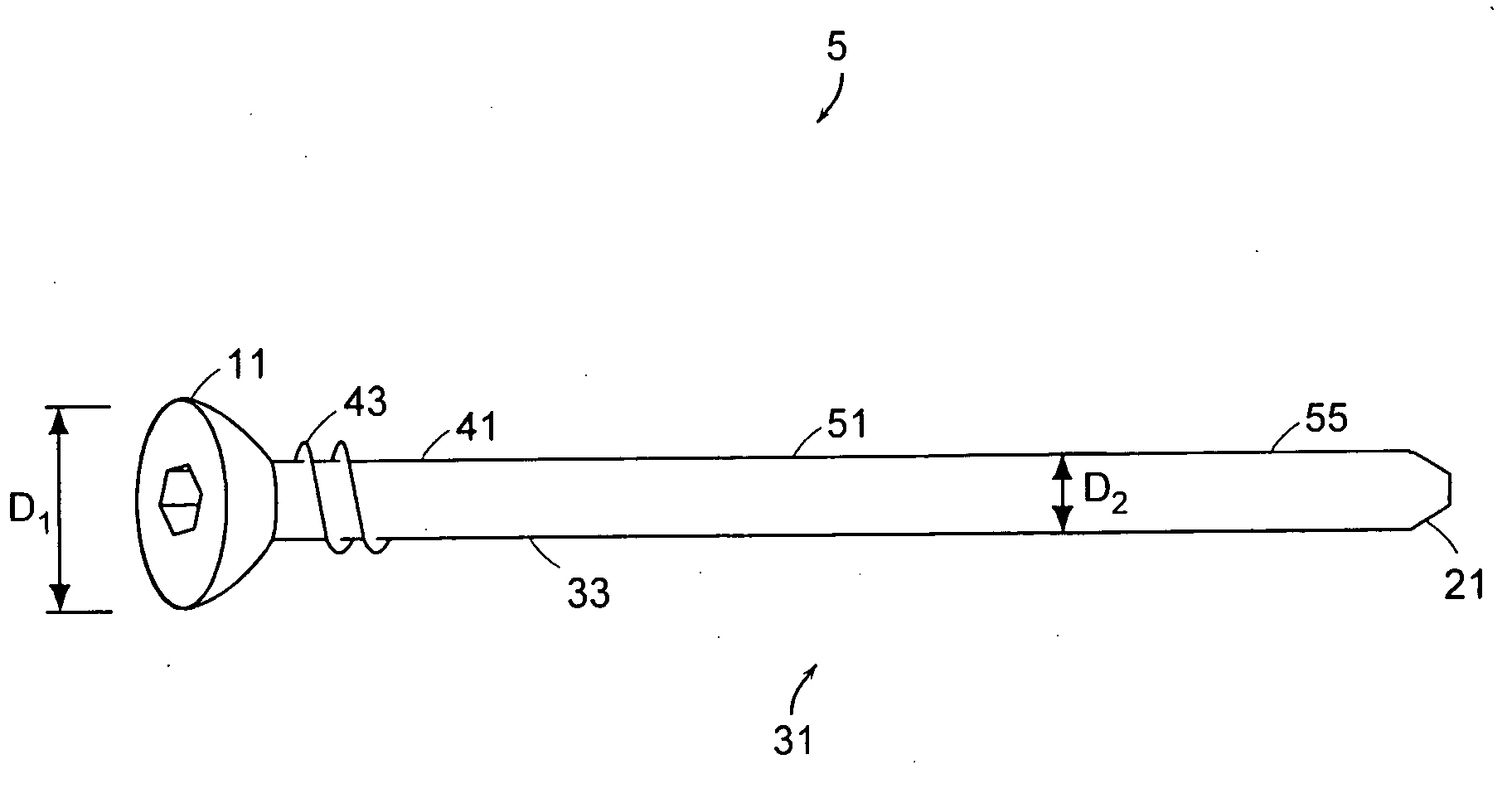
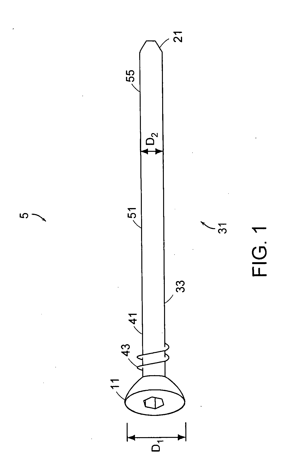
[0035] Referring now to FIG. 1, there is provided a bone fixation system 1 comprising a pin 5 comprising: [0036] a) a proximal head 11 having a first maximum diameter D1, [0037] b) a distal tip 21, and [0038] c) a substantially cylindrical intermediate shaft portion 31 having an outer surface 33 defining a second maximum diameter D2, the shaft portion comprising: [0039] i) a proximal portion 41 having fastening surface 43 extending no more than 25% of the shaft length, and [0040] ii) a smooth central portion 51, and [...


PUM


Abstract

A facet joint fixation system that provides initial rigidity for stabilizing the facet joint, is sufficiently strong to withstand facet joint shear stresses, and (after supporting a successful fusion) can be resorbed by the body.

Description

BACKGROUND OF THE INVENTION [0001] Current spine fusion procedures rely heavily on the use of anteriorly-placed cages and posterior fixation to achieve the necessary stability and rigidity to obtain successful clinical results. Accordingly, conventional posterior instrumentation used to augment a spinal fusion primarily includes metallic facet screws, translaminar facet screws, and postero-lateral pedicle screw-plate systems. In some system, rods replace the above-mentioned plates. Because implantation of posterior instrumentation including pedicle screws necessarily involves removing important musculoskeletal elements, there is heightened interest in developing improved systems based upon facet screws. [0002] Facet screws have long been used as an alternative to pedicle fixation screws. For example, Published PCT Patent Application No. WO 00 / 62684 (“Marino”) discloses a method of securing facet joints by drilling a hole through the joint and inserting a conventional facet screw. U....

Claims


Application Information

Patent Timeline
IPC IPC(8): A61B17/00A61B17/56A61B17/70
CPCA61B2017/00004A61B17/7064
Inventor SERHAN, HASSANDINELLO, ALEXANDRE MICHELSLIVKA, MICHAEL ANDREW
Owner DEPUY SPINE INC (US)
Why Eureka
Try Eureka