Valve body and seal assembly

Inactive Publication Date: 2005-10-18
S P M FLOW CONTROL
View PDF11 Cites 29 Cited by
  • Summary
  • Abstract
  • Description
  • Claims
  • Application Information

AI Technical Summary

Benefits of technology

[0029]Serrations (or serration groups) on first and second groove walls are therefore offset. Serration offset, in turn, minimizes the detrimental stress-raising effects of the serrations on their respective valve body flange areas. Additionally, use of offset serrations means that retaining forces exerted on an elastomeric seal in a groove by serrations on the opposing groove walls are further spaced apart as a function of the offset distance. This further spacing apart adds to the separation of forces acting on the seal and thus reduces stress concentration in the seal elastomer that would tend to tear the seal apart. Reduced stress concentration, in turn, results in reduced elastomer stress for seals in the present invention compared with seals illustrated in the '299 and '481 patents (where serrations are not offset but instead are directly opposite each o

Problems solved by technology

They are relatively stiff for their weight, and do not employ any means such as a seal

Method used


Image

  • Valve body and seal assembly
  • Valve body and seal assembly
  • Valve body and seal assembly

Examples


Example

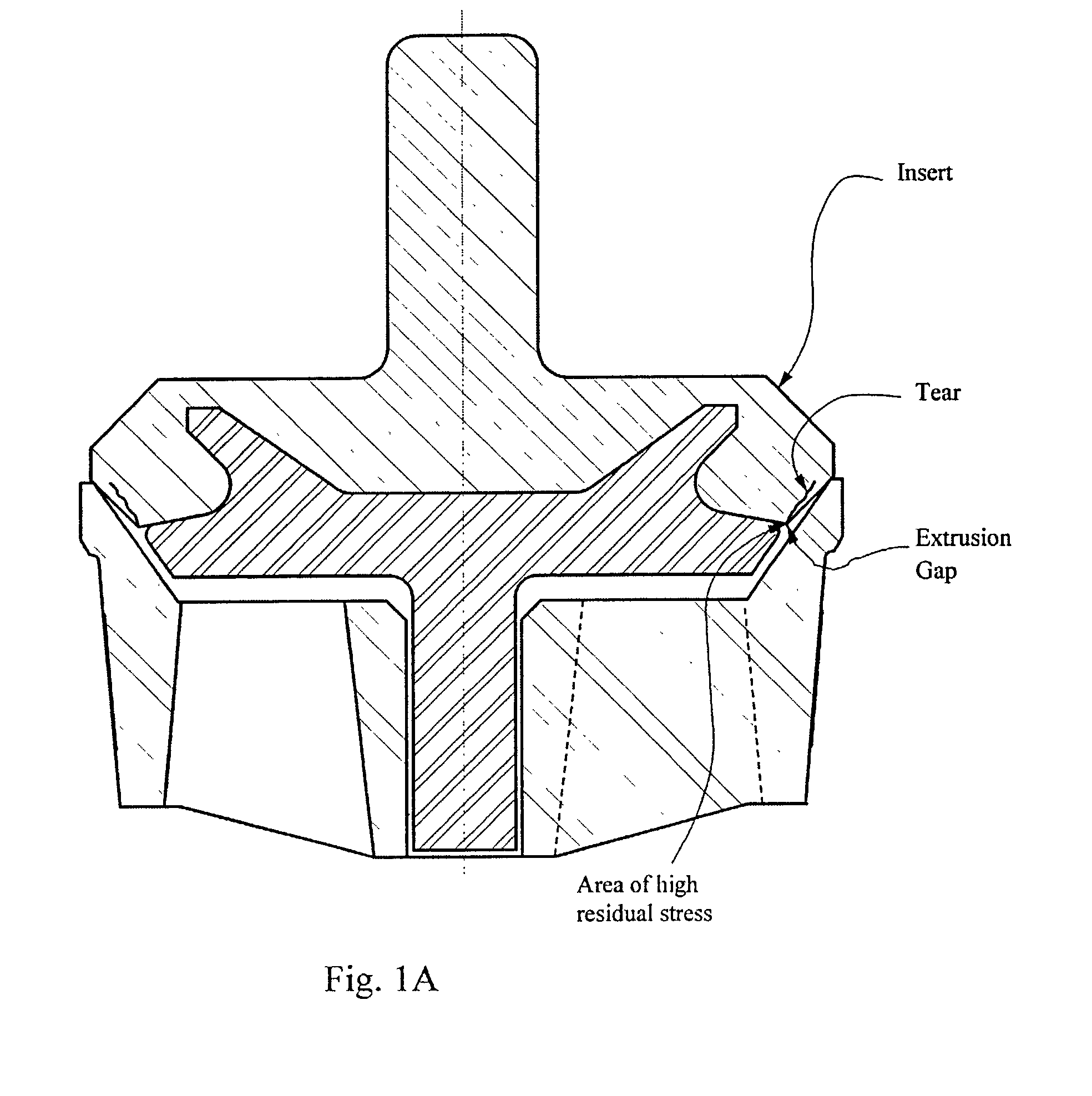
[0040]FIG. 1A indicates typical areas of high elastomer stress and associated premature seal failure expected in bonded seals on valve bodies like that in FIG. 2 of the '995 patent. Note that the '995 patent does not discuss seal failure due to high elastomer stress at all. On the contrary, by describing increased overall valve element integrity associated with the bonding of valve seal inserts to a valve body, the '995 patent teaches away from the adhesion-inhibiting structures and functions of the present invention.

[0041]In so teaching, the '995 patent simply reinforces the past failure of valve manufacturers to appreciate the important effects of seal elastomer background stress on valve durability. Until the present invention, the problem of elevated background elastomer stress in bonded seals was neither recognized nor effectively addressed. Indeed, the problem was actually compounded by the widespread industry practices reflected in the teachings of the '995 patent.

[0042]In co...


PUM


Abstract

A valve seal assembly comprising a valve body having one or more peripheral integral seal retention grooves and one or more peripheral elastomeric seals, each seal being cast-in-place in an integral seal retention groove having adhesion-inhibiting surfaces and offset circular serrations of predetermined height on opposing groove walls. Adhesion-inhibiting surfaces reduce or eliminate internal elastomer stress due to curing of cast-in-place elastomeric seals. Serrations on each of the opposing groove walls are offset to accommodate differing stress concentrations in the walls. Opposing groove walls preferably diverge peripherally. Offset serrations result in decreased metal fatigue from impact and bending stress. Offset serrations also improve valve sealing and increase valve service life by maintaining correct seal position on the valve body while minimizing background stress in the seal elastomer. In representative valve applications, serration height is preferably predetermined so that the cured elastomeric seal remains interdigitated with the serrations for greater than half of the predetermined serration height.

Description

[0001]This is a continuation-in-part (CIP) patent application of U.S. Ser. No. 09 / 836,043, which was filed Apr. 16, 2001 ABN.FIELD OF THE INVENTION[0002]The present invention relates generally to valves suitable for rapid open-close cycling with abrasive fluids, such as drilling mud, under high pressures. More specifically, the invention relates to valves comprising an elastomeric seal in a peripheral seal retention groove on the moving element of the valve.BACKGROUND OF THE INVENTION[0003]Valve terminology varies according to the industry (e.g., pipeline or oil field service) in which the valve is used. In some applications, the term “valve” means just the moving element, whereas in other applications, the term “valve” includes the moving element, the valve seat, and the housing that contains the moving element and the valve seat. To clarify the following description of the present invention, a valve suitable for abrasive fluids, such as oil field drilling mud, comprises a valve bo...

Claims


Application Information

Patent Timeline
IPC IPC(8): F16K15/06F16K15/02F16K1/38
CPCF16K1/38Y10S137/902Y10T137/0491F16K15/06
Inventor BLUME, GEORGE H.
Owner S P M FLOW CONTROL
Why Eureka
Try Eureka