Method of varying the temperature of a tube bundle reactor

a technology of a tube bundle and a reactor, which is applied in the direction of indirect heat exchangers, lighting and heating apparatus, and tubular conduit assemblies. it can solve the problems of high investment costs, high cost of heating units and accessories, undue deformation or even cracking of surrounding walls, etc., and achieves the effect of prolonging the life, simple mechanical outfitting of the reactor system, and easy and reliable operation

Inactive Publication Date: 2008-01-31
MAN DWE
View PDF1 Cites 33 Cited by
  • Summary
  • Abstract
  • Description
  • Claims
  • Application Information

AI Technical Summary

Benefits of technology

[0035] It is a fact that the method according to the invention unambiguously defines variables and points of measurement—temperature and / or volume flow of the temperature gas at the inlet into the reactor tubes and time-average temperature rate of change of the temperature gas at the outlet from the reactor tubes—these variables being measured either directly or indirectly. Therefore, a person skilled in the art can ascertain easily and reliably, during start-up and shut-down operations, whether he is in the safe or unsafe region as regards the thermal loads.
[0036] The method according to the invention, on the one hand, allows the reactor system to be started up and shut down quickly while, at the same time, guaranteeing that this can be achieved smoothly and safely in consideration of inadmissible thermal stresses. Subsequently, several load cycles may be run; the lifetime is prolonged. Furthermore, the mechanical outfit of the reactor system is simplified by the provision of only one expansion tank to receive heat transfer medium material as it expands with rising temperatures. A separate reservoir can be dispensed with.
[0037] The limitation of the time-average temperature rate of change of the temperature gas also permits more accurate dimensioning of the heat-up means, and that helps to save investment cost.

Problems solved by technology

Such a design is disadvantageous in that either an additional circulating means is required in the heat exchanger circuit or control means must be installed in the main conduit extending parallel to the heat exchanger so that the heat transfer medium proportion flowing through the heat exchanger circuit will be adjustable.
The consequence of this choice would be a stronger circulating means and thus higher investment costs.
In that case the expanding salt could cause undue deformation or even cracking of the surrounding walls.
It is said in DE 2 062 095 134 that vapor of sufficiently high temperature was available only rarely, whereas hot air and flue gases required a lot of expenditure in terms of heating units and accessories or led to operational deficiencies.
That may cause inadmissible thermal stress, going so far as to damage or even destroy the reactor.
Moreover, it is disadvantageous to continue to heat the reactor with gas when the melting temperature of the heat transfer medium has long been reached and the reactor already is filled with liquid heat transfer medium salt.
During normal operation between lower and upper operating points, temperature variations may occur in the heat transfer medium system and that may cause volume variations of the heat transfer medium.
For its heat-up, this reactor system requires an expensive measuring, control, and regulating system for the volume flows and temperatures.
With them, however, a person skilled in the art does not know at what points these must be observed and, therefore, fails to know when in fact they are surpassed.
Moreover, start-up and shut-down of accessory units directly coupled to the tube bundle reactor are not considered in the prior art.

Method used


Image

  • Method of varying the temperature of a tube bundle reactor
  • Method of varying the temperature of a tube bundle reactor
  • Method of varying the temperature of a tube bundle reactor

Examples


first embodiment

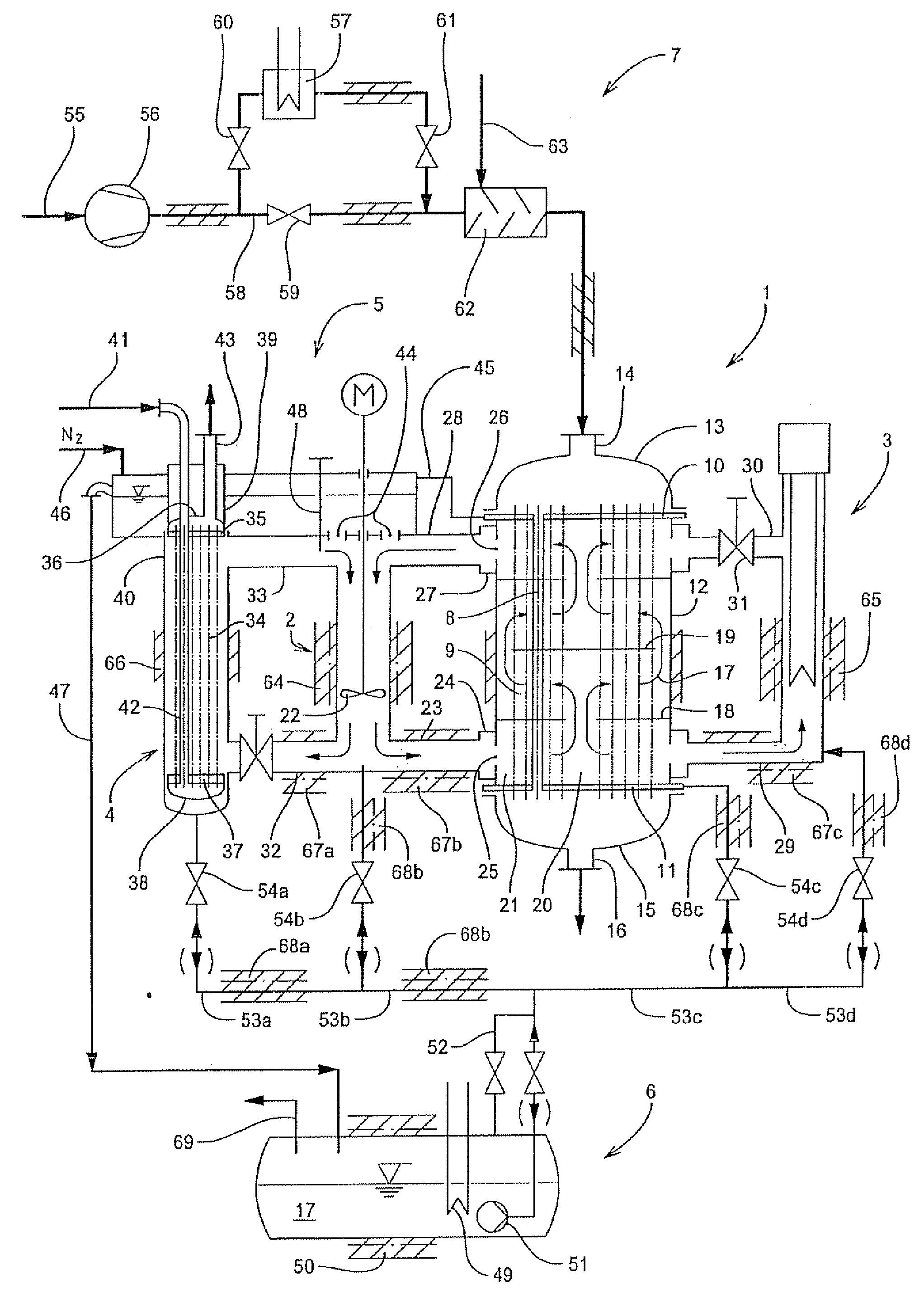
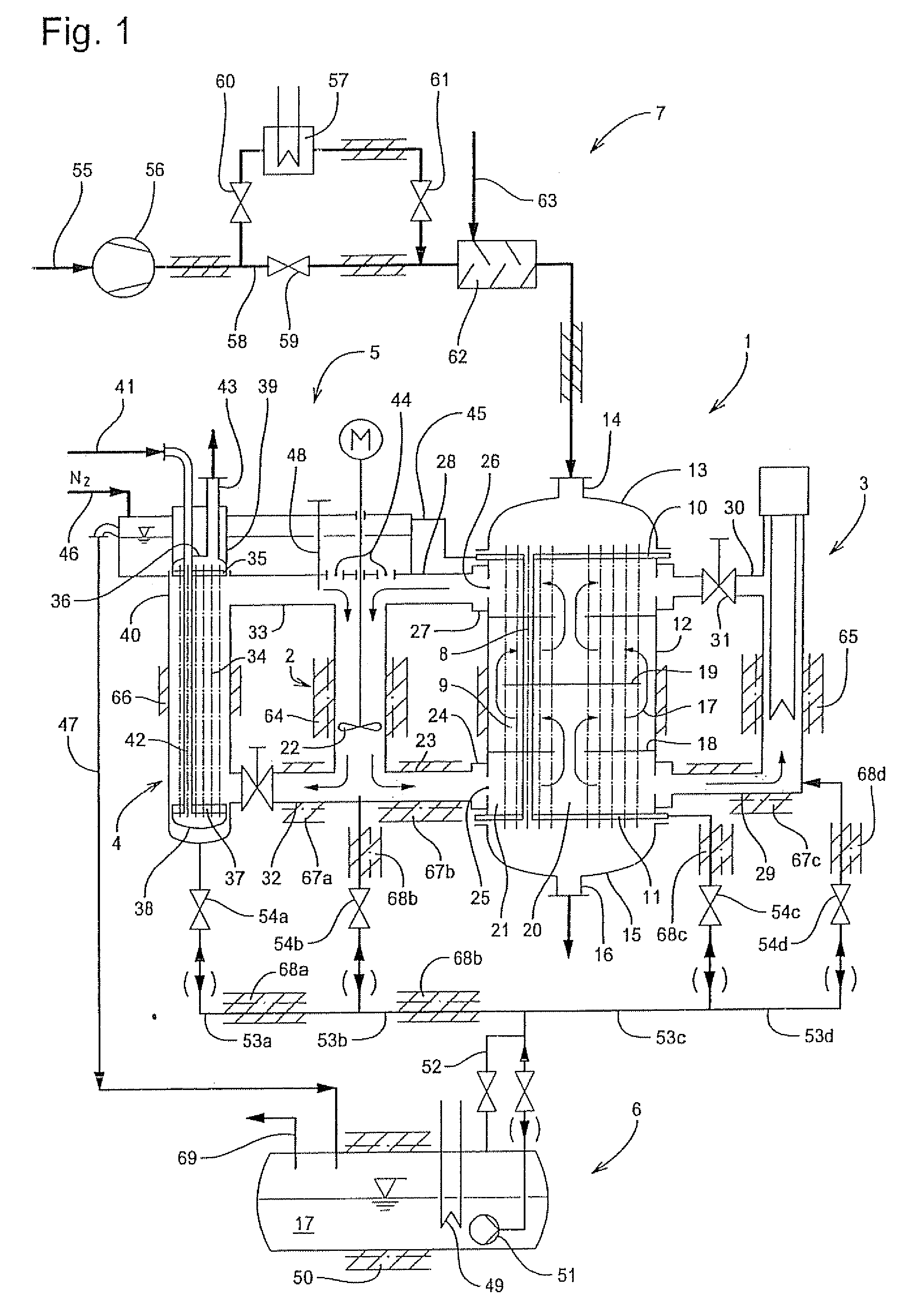
[0219]FIG. 1 illustrates a reactor system for the method according to the invention. The reactor system is designed for exothermic gas phase reactions. The heat transfer medium used is salt. The principal component parts of this reactor system, shown as an example, essentially are a single-zone reactor 1, a circulating means 2, a heat-up means 3, a cooler 4, an expansion tank 5, a salt tank 6, and a gas treatment apparatus 7 for producing a temperature gas and a reaction gas mixture, respectively.

[0220] In the embodiment illustrated, the reactor 1 is embodied by a tube bundle reactor. It comprises a plurality of catalyst-filled reactor tubes 8 which form a tube bundle 9. The reactor tubes 8 terminate in sealed fashion in an upper tubesheet 10 and in a lower tubesheet 11. The tube bundle 9 is enclosed by an insulated shell 12 connected to the upper tubesheet 10 and the lower tubesheet 11. If desired, the shell 12 may comprise compensators (not shown) for accommodating thermal stresse...

second embodiment

[0260]FIG. 6 shows a variant of the reactor system of FIG. 1 as application of the method according to the invention. While the reactor system shown in FIG. 1 comprises a single-zone reactor 1, the reactor system presented in FIG. 6 comprises a dual-zone reactor 1′ whose two zones 100, 100′ are separated by a partition 101. For the sake of avoiding repetitions, only alterations in comparison with the reactor system illustrated in FIG. 1 will be described below. As for the rest, reference is made to the description of FIG. 1.

[0261] The heat tracing means and insulations are not demonstrated in FIG. 6. They are, however, similar to those provided in the reactor system according to FIG. 1.

[0262] In the reactor system according to FIG. 6, each of the two zones 100, 100′ has its own apparatus group of circulating means 2, 2′ / cooler 4, 4′ / optional bypass. A connecting line 102 links the heat transfer medium spaces in the two zones at places of different pressures. In the illustrated embo...


PUM


Abstract

A method of varying the temperature of a tube bundle reactor for catalytic gas phase reactions upon start-up and shut-down, the tube bundle reactor comprising a major reactor portion which includes a bundle of vertically disposed reactor tubes, upper and lower tubesheets tightly connected to the upper and lower ends, respectively, of the reactor tubes, and a reactor shell enclosing the tube bundle, a heat transfer medium having a melting temperature in the range of from 100° C. to 450° C. flowing around the outer surfaces of the reactor tubes during normal operation and being circulated in at least one circuit through the major reactor portion, comprising the steps: (a) varying the heat transfer medium temperature during circulation of the heat transfer medium; and (b) passing a temperature gas through the reactor tubes at least when the heat transfer medium is not yet or no longer circulated.

Description

FIELD OF THE INVENTION [0001] The invention relates to a method of varying the temperature of a tube bundle reactor for catalytic gas phase reactions upon start-up and shut-down. BACKGROUND OF THE INVENTION [0002] In the chemical industry, catalytic gas phase processes, such as oxidation, hydrogenation, dehydrogenation, nitration, alkylation are performed successfully in tube bundle reactors comprising packed beds. Tube bundle reactors of this kind are known, for example, from DE 2 207 166 B4. [0003] The reaction, in principle, may be either endothermic or exothermic. The packed bed, essentially a granular type catalyst, is located in a vertically positioned, generally ring-like bundle of reactor tubes which are sealed at both ends and fixed in tubesheets. The reaction gas mixture (feed gas) is supplied to the reactor tubes through a reactor head which spans the respective tubesheet, and it is likewise discharged (as a product gas mixture) through a reactor head spanning the other t...

Claims


Application Information

Patent Timeline
Patent Type & Authority Applications(United States)
IPC IPC(8): B01J8/06
CPCB01J8/067B01J2208/00053B01J2208/00061B01J2208/00212F28F27/00B01J2208/00256B01J2208/00646B01J2208/00716F28D7/16B01J2208/00221
Inventor LEHR, MANFREDDACHS, JOSEFSCHUSTER, WOLFGANG
Owner MAN DWE
Why Eureka
Try Eureka