Transluminal methods and devices for closing, forming attachments to, and/or forming anastomotic junctions in, luminal anatomical structures

a technology of transluminal devices and luminal anatomical structures, applied in the field of transluminal devices, can solve the problems of blood leakage into, graft may undergo undesirable migration or slippage, etc., and achieve the effect of occlude luminal anatomical structures and enhance their engagement or gripping of anatomical structures

Inactive Publication Date: 2006-06-06
MEDTRONIC VASCULAR INC
View PDF29 Cites 229 Cited by
  • Summary
  • Abstract
  • Description
  • Claims
  • Application Information

AI Technical Summary

Benefits of technology

[0009]In accordance with a first embodiment of the invention, there is provided an intraluminal device which is useable to occlude luminal anatomical structure by way of a closure device referred to herein, for purposes of convenience only, as a “clock spring” occluder. This device comprises an elongate catheter which is insertable into a luminal structure, and a resilient coil which is advancable out of the catheter and at least partially through the wall of the luminal anatomical structure to occlude the lumen of the anatomical structure. This resilient coil may optionally have one or more engagement members (e.g., barbs or hooks) formed thereon to enhance its engagement or gripping of the anatomical structure and to prevent the coil from slipping or pulling back through the puncture tract through which it is advanced into or through the anatomical structure wall. Generally, a first end of the resilient coil is advancable out of the catheter and at least partially through the wall of the luminal structure (e.g., blood vessel) within which the catheter is positioned. Thereafter, the coil is further advanced within or outside of the wall of the anatomical structure so as to fully or partially encircle or surround the lumen of the anatomical structure (e.g., it may slidably advance around the adventitial surface of a blood vessel). The optional engagement members (hooks or barbs), if present, will protrude into, grip, adhere to or otherwise engage the wall of the luminal anatomical structure in a manner which will prevent the coil from slipping or pulling back through the puncture tract which it has formed into or through the anatomical structure wall and / or to prevent the from uncoiling in any way which would cause the lumen of the anatomical structure to return to its open configuration.

Problems solved by technology

However, in the event that these stent(s) fail to establish sound frictional engagement with the blood vessel wall, the graft may undergo undesirable migration or slippage, or blood may leak into the anneurysmic sac (sometimes referred to as an “endoleak”).

Method used


Image

  • Transluminal methods and devices for closing, forming attachments to, and/or forming anastomotic junctions in, luminal anatomical structures
  • Transluminal methods and devices for closing, forming attachments to, and/or forming anastomotic junctions in, luminal anatomical structures
  • Transluminal methods and devices for closing, forming attachments to, and/or forming anastomotic junctions in, luminal anatomical structures

Examples


first embodiment

i. Clock Spring Occluder

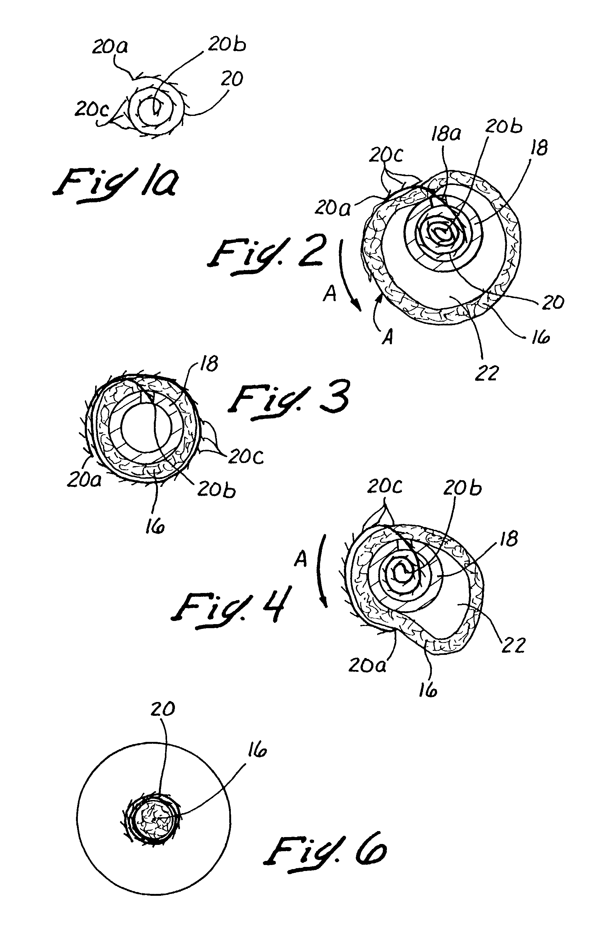
[0055]A clock spring occluder 20, more clearly seen in FIG. 2a, comprises a generally spiral-shaped coil having a first outwardly oriented end 20a and a second inwardly oriented end 20b. The clock spring occluder may further have a multiplicity of outwardly extending engagement members, such as protrusions or barbs 20c which, as will be discussed below, enhance the ability of the occluder 20 to securely grasp and occlude the lumen of an anatomical structure such as a blood vessel.

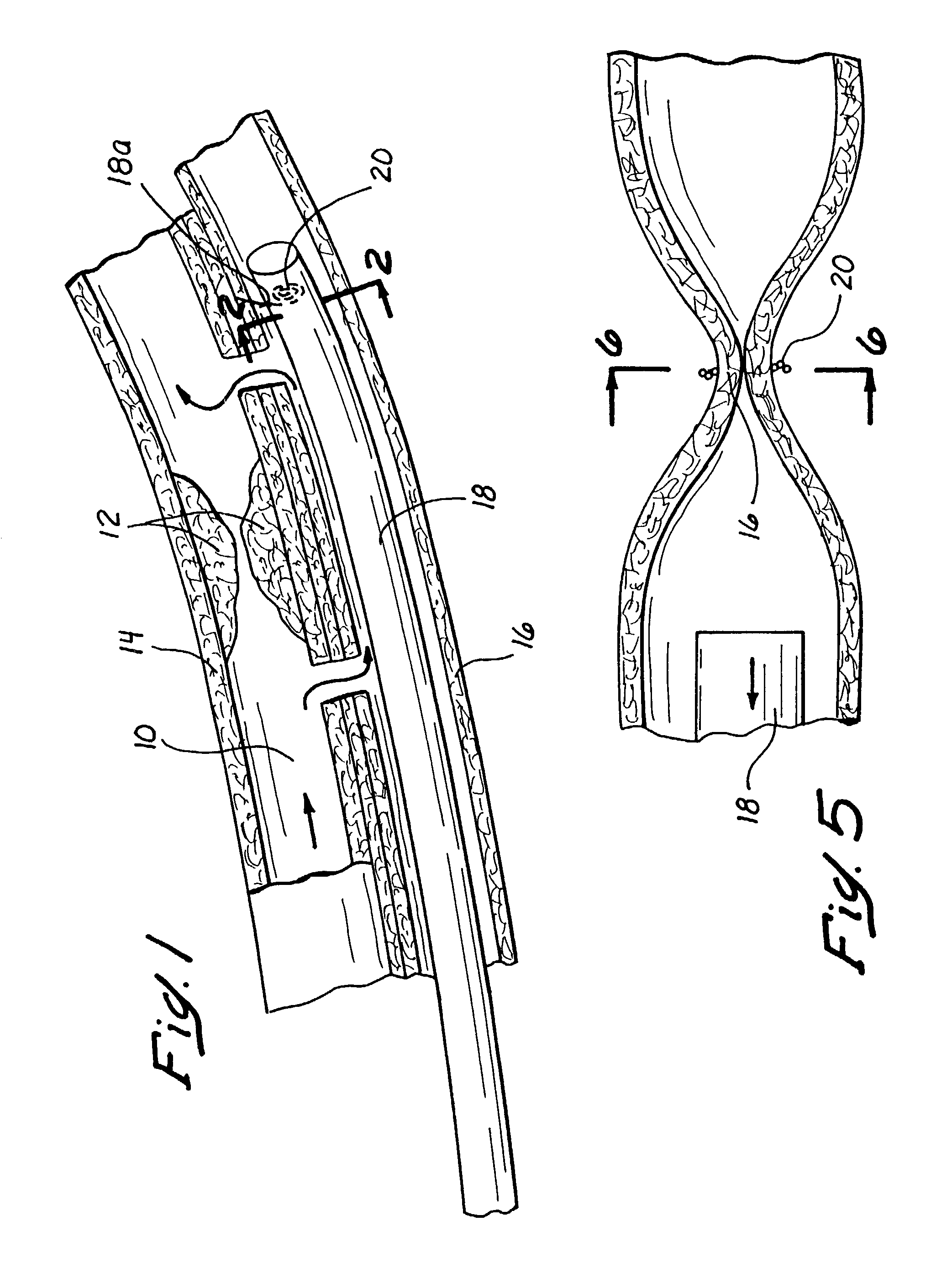
[0056]The clock spring occluder 20 is deployed through the lumen of the catheter 18, as shown schematically in FIG. 1. The catheter 18 is inserted and positioned within the vessel 16 such that side opening 18a formed at the distal end of the catheter 18 is aligned with and juxtapositioned with a portion of the vessel wall 16, at the location where it is desired to occlude the vessel. The first outwardly oriented end 20a of the clock spring occluder 20 is then advanced through the sid...

second embodiment

ii. T-Occluder Apparatus

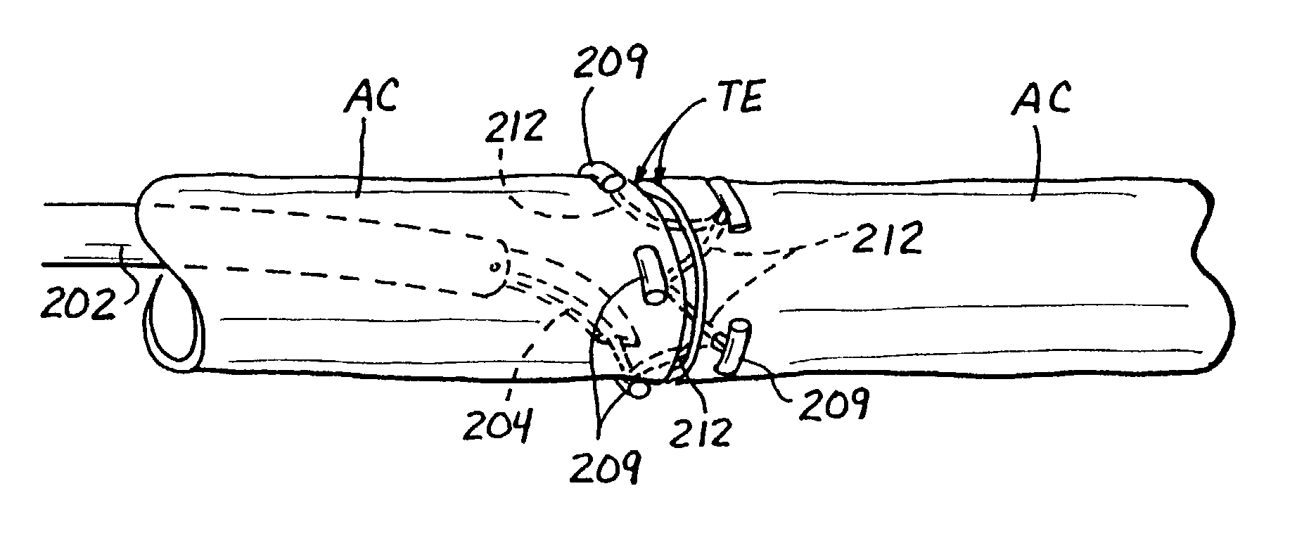
[0059]FIGS. 7–11 and 23–23b show a second embodiment of a transluminal device 24 which is useable for ligating a luminal structure, such as a blood vessel, or for the other applications such as anchoring or attaching an endoluminal graft or other endoluminal apparatus to the wall of the luminal structure (e.g., blood vessel).

[0060]This second embodiment of the intraluminal device 24 comprises an elongate rigid or pliable catheter 26 having a first lumen 26a and a second lumen 26b extending longitudinally therethrough. A hollow needle 28, which has an elongate slot 28b formed in one side thereof adjacent its distal end 28a, is slidably disposed within the first lumen 26a of the catheter 26 so as to be advancable out of the catheter, as shown. The second lumen 26b may be used for passage of a guidewire, to permit the catheter 26 to be advanced over a pre-positioned guidewire.

[0061]Disposed within the hollow bore of the curved needle 28 is a T-occluder apparatus...

third embodiment

iii. Twist Clip Apparatus

[0067]Referring now to FIGS. 16 and 17, there is shown a third embodiment on an intraluminal apparatus for occluding blood flow at a specific site within a luminal anatomical structure such as a blood vessel. As shown in FIG. 16, third embodiment may comprise an elongate rigid or pliable catheter 38 having a hollow lumen extending longitudinally therethrough and a side opening 38a formed near its distal end. Disposed within the lumen of the catheter 38 is a twist clip 42. The twist clip 42 is formed of malleable material and comprises a first straight section 42a and a second section 28b, which extends generally perpendicular to the first straight section 42a. An outwardly curved tip 42c is formed on the distal end of the second section 42b. As illustrated, the twist clip 42, and more particularly the outwardly curved tip 42c thereof, is initially advanced some distance out of the side opening 38a and to pierce through the vessel wall 40. Thereafter, the cat...


PUM


Abstract

Methods and apparatus for passing attachment apparatus (e.g., connector devices, staples, etc.) or connector material (e.g., suture thread, wire, cord, filament, monofilament, etc.) into or through the wall of a luminal anatomical structure (e.g., a blood vessel or other anatomical conduit) for the purpose of; i) closing the lumen of the anatomical structure, ii) forming an anastomotic junction between separate anatomical structures (or between approximated segments of the same anatomical structure), and/or iii) attaching an article (e.g., an endoluminal, extraluminal or transluminal graft) or other apparatus to the wall of the anatomical structure.

Description

[0001]This is a divisional of application Ser. No. 09 / 908,337 filed on Jul. 18, 2001 now U.S. Pat. No. 6,491,707 which is a divisional of application Ser. No. 09 / 543,251 filed on Apr. 5, 2000 now U.S. Pat. No. 6,287,317, which is a division of Ser. No. 08 / 896,307 filed on Jun. 28, 1997 issued U.S. Pat. No. 6,071,292 filed on Jun. 28, 1977 issued on Jun. 6, 2000.FIELD OF THE INVENTION[0002]The present invention relates generally to medical devices and methods, and more particularly to intraluminal devices and methods for passing attachment apparatus (e.g., connector devices, staples, etc.) or connector material (e.g., suture thread, wire, cord, filament, monofilament, etc.) into or through the wall of a luminal anatomical structure (e.g., a blood vessel or other anatomical conduit) for the purpose of; i) closing the lumen of the anatomical structure, ii) forming an anastomotic junction between separate anatomical structures (or between approximated segments of the same anatomical str...

Claims


Application Information

Patent Timeline
Patent Type & Authority Patents(United States)
IPC IPC(8): A61B17/04A61B17/00A61B17/06A61B17/064A61B17/11A61B17/12
CPCA61B17/0401A61B17/06A61B17/064A61B17/11A61B17/12A61B2017/1135A61B17/12013A61B2017/00292A61B2017/00557A61B2017/0409A61B2017/0419A61B2017/0454A61B2017/0458A61B2017/0464A61B2017/06047A61B2017/1107A61B17/0482A61B17/0469A61B2017/00946A61B2017/1139
Inventor MAKOWER, JOSHUAFLAHERTY, J. CHRISTOPHERMACHOLD, TIMOTHY R.GARIBOTTO, JOHN THOMASWHITT, JASON BRIAN
Owner MEDTRONIC VASCULAR INC
Why Eureka
Try Eureka