Multi-piece clamp for standing seams

a multi-piece, standing seam technology, applied in the field of metal surfaces, can solve the problems of time required to complete the installation, inconvenience of installation, and the manner in which it must be installed on the standing seam, and achieve the effect of increasing the amount of force and increasing the resistan

Inactive Publication Date: 2006-09-05
CAUGHT FISH ENTERPRISES +1
View PDF25 Cites 112 Cited by
  • Summary
  • Abstract
  • Description
  • Claims
  • Application Information

AI Technical Summary

Benefits of technology

[0012]Various refinements exist of the features noted in relation to the first aspect of the present invention. Further features may also be incorporated in the first aspect of the present invention as well. These refinements and additional features may exist individually or in any combination. Having the clamp of the first aspect be defined at least in part by a clamp body and at least one separate insert provides a number of benefits. Initially, this may allow the clamp of the first aspect to be installed on a standing seam without having to slide the clamp onto an end of the standing seam. This is particularly beneficial in cases where the distal extreme or head of the standing seam has a relatively wide profile in relation to a portion of the standing seam that extends outwardly from (e.g., vertically upward) adjacent portions of the panel assembly. Representative standing seam profiles of this type include a “bulbous seam” panel, a “T” seam profile, an inverted “L” seam panel, and the like. In this case, at least a portion of the first insert used by the first aspect may be disposed anywhere below the enlarged head of sorts of the standing seam to in effect almost completely enclose the enlarged head of the standing seam within a cavity that is defined at least in part by the walls of the clamp body slot, the first insert, or a combination thereof Another benefit of the clamp of the first aspect is that it allows a single clamp body to be configured so as to be usable with inserts of various sizes, configurations, or both. The clamp of the first aspect may then be used with different standing seam profiles by using the same clamp body, and then by simply changing the insert(s).
[0021]Additional features that may be utilized by the clamp of the first aspect of the present invention is some way to register the first insert in a predetermined position relative to the clamp body, preferably during installation. One way in which this may be done and which provides for an enhanced engagement of the first insert and the clamp body is to include one or more contours on an interface between the first insert and that portion of a clamp body slot wall that is engaged by the first insert (e.g., to provide something other than a continuous planar interface). In one embodiment, a wall of the clamp body slot that interfaces with the first insert includes a groove, and a wall of the first insert that interfaces with the clamp body slot includes a bead, rail, rib, or other protrusion that may be disposed within this groove, or vice versa. This not only registers the first insert in a predetermined position relative to the clamp body, but also increases the amount of forces which would be required to introduce relative movement between the clamp body and the first insert in a direction which is at least generally directed away from the standing seam on which the clamp of the first aspect is installed. That is, this particular way of registering the first insert in a predetermined position on a clamp body slot wall also increases the amount of resistance that the clamp of the first aspect has to a shearing-like action to which the clamp may be exposed when installed on a standing seam (e.g., a force which would tend to pivot the clamp off of the standing seam in a direction that is at least generally parallel with the axial extent of the standing seam).

Problems solved by technology

One of the primary disadvantages of the clamp 26 of FIG. 3 is the manner in which it must be installed on a standing seam.
The time required to complete the installation and the inconveniences associated with this installation may detract from the usage of these types of clamps.

Method used


Image

  • Multi-piece clamp for standing seams
  • Multi-piece clamp for standing seams
  • Multi-piece clamp for standing seams

Examples


Embodiment Construction

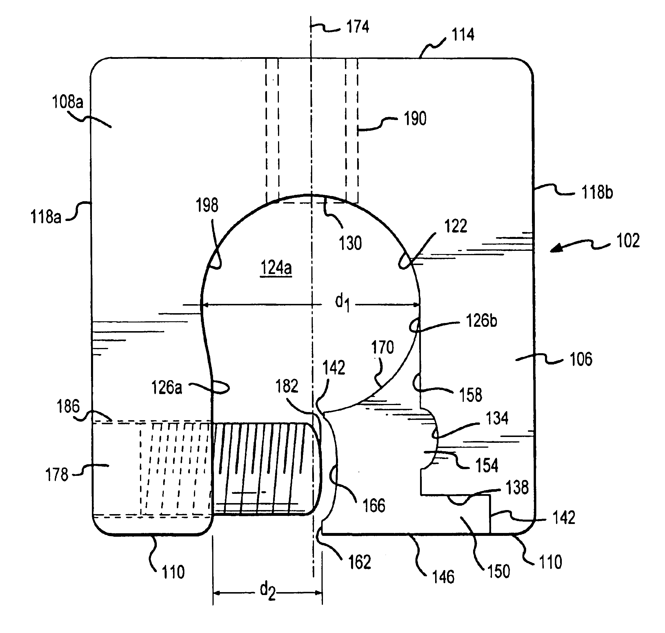
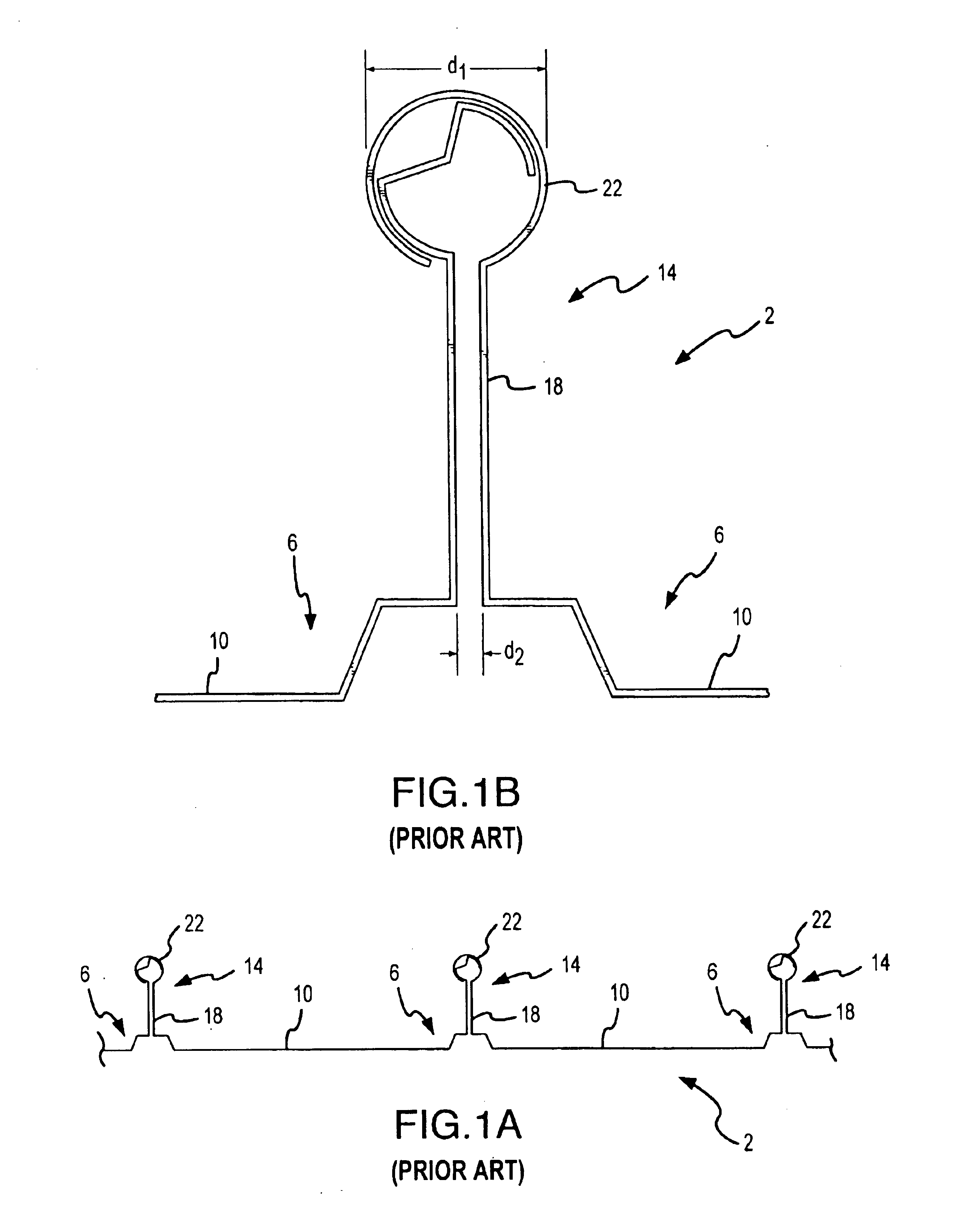
[0050]The present invention will now be described in relation to the accompanying drawings which at least assist in illustrating its various pertinent features. FIGS. 5A-C present a clamp 102 that may be used with a standing seam profile of at least generally the type used by the panel assembly 2 of FIGS. 1A-C. For convenience, the clamp 102 will be described in relation to the standing seam 14. The clamp 102 generally includes a unitary or one-piece clamp body 106. Preferably the clamp body 106 is an extrusion of a material that is appropriate for the desired application of the clamp 102, such as aluminum, brass, or zinc. Other manufacturing techniques could also be utilized for making the clamp body 106, such as casting or machining. Extruding the clamp body 106 provides a number of advantages, including ease of manufacture and structural strength.

[0051]The clamp body 106 is defined by a pair of clamp body ends or end surfaces 108a, 108b that are longitudinally spaced (i.e., space...


PUM


Abstract

A multi-piece clamp for installation on a standing seam is disclosed. One component of the clamp is a clamp body with a clamp body slot formed therein. This slot is mounted on a standing seam without having to slide the clamp body onto an end of the seam. Another component of the clamp is at least one insert, where each such insert is disposed within the clamp body slot between a clamp body slot wall and the standing seam. One or more seam fasteners are directed through the clamp body and a clamp body slot wall to secure each of the inserts within the clamp body slot by a compression of the same, and further to secure the clamp to the standing seam.

Description

CROSS-REFERENCE TO RELATED APPLICATIONS[0001]This patent application claims priority from and is a continuation of U.S. patent application Ser. No. 09 / 758,805, filed Jan. 11, 2001, now abandoned and incorporated by reference in its entirety herein; which is a continuation-in-part of U.S. patent application Ser. No. 09 / 698,358, filed Oct. 27, 2000, now abandoned; which is a continuation of U.S. patent application Ser. No. 09 / 312,013, filed May 14, 1999, now U.S. Pat No. 6,164,033, issued Dec. 26, 2000; which is a continuation of U.S. patent application Ser. No. 08 / 987,368, filed Dec. 9, 1997, now U.S. Pat. No. 5,983,588, issued Nov. 16, 1999; and which is a continuation of U.S. patent application Ser. No. 08 / 482,274, filed Jun. 7, 1995, now U.S. Pat. No. 5,715,640, issued Feb. 10, 1998.FIELD OF THE INVENTION[0002]The present invention generally relates to metal surfaces that are defined by a plurality of interconnected panels that in turn define a plurality of standing seams and, mor...

Claims


Application Information

Patent Timeline
Patent Type & Authority Patents(United States)
IPC IPC(8): E04D1/34E04D3/36E04D13/10E04G21/32
CPCE04D3/3608E04G21/3261E04D13/103E04D13/10E04G21/3276E04G21/3285
Inventor HADDOCK, ROBERT M. M.
Owner CAUGHT FISH ENTERPRISES
Why Eureka
Try Eureka