Facet joint fusion devices and methods

a facet joint and fusion technology, applied in the field of medical devices, methods and systems, can solve the problems of inability to achieve conservative treatment in a significant number of spinal pain patients, inability to apply compressive force to the cinchable tether, and inability to achieve fusion and/or stabilization of one or more facet joints. , to achieve the effect of promoting fusion and/or stabilization, enhancing the ability of the cinchable tether to apply compress

Inactive Publication Date: 2011-05-03
ALAMIN TODD F +1
View PDF71 Cites 113 Cited by
  • Summary
  • Abstract
  • Description
  • Claims
  • Application Information

AI Technical Summary

Benefits of technology

[0012]Methods, devices and systems of the present invention promote fusion of and / or stabilize an intervertebral facet joint. Methods generally involve clamping two vertebrae across a facet joint to apply compressive force to the joint. Devices include one or more cinchable tethers, which in various embodiments may be passed through a hole extending through two vertebrae and / or may circumscribe the two vertebrae. Some embodiments also include one or more bone surface contacting members, such as plates, washers or the like, which enhance the ability of the cinchable tether to apply compressive force. One advantage of various embodiments of the invention is that they may be used to promote fusion and / or stabilization of one or more facet joints using a minimally invasive or less invasive procedure. In various embodiments, either percutaneous or open surgical approaches may be used. In a number of embodiments, techniques and devices of the invention may be used with other currently available devices or systems.
[0014]In some embodiments, the hole extends through a first of the two vertebrae along a first axis and through a second of the two vertebrae along a second axis, so that advancing the tether through the hole causes the vertebrae to translate relative to each other. This “offset-hole” technique allows a surgeon to realign the vertebrae while also promoting fusion of and / or stabilizing the joint. In some embodiments, two holes are formed through the two vertebrae across the facet joint, and a separate tether is advanced through each of the two holes. Alternatively, two holes may be formed through the two vertebrae across the joint, and one tether may be advanced through both holes. In various other embodiments, any other suitable combination of holes and tether(s) may be used.
[0015]Optionally, a first bone surface contacting member slidably coupled with the tether may be contacted with a first of the two vertebrae, before the cinching step. The method may further comprise contacting a second bone surface contacting member slidably coupled with the tether with a second of the two vertebrae, also before the cinching step. One or more bone contacting members, such as plates, washers or the like, may help distribute force applied by the cinchable tether to more effectively apply compressive force across the joint.
[0017]In some embodiments, rather than forming a hole through the vertebrae, clamping may involve circumscribing the joint with a tether disposed over the vertebrae. In some cases, such a tether may be cinchable for applying the compressive force. Optionally, the method may further include contouring external surfaces of the vertebrae to enhance engagement of the tether with the surfaces.

Problems solved by technology

The direct costs of treating back pain, as well as the indirect costs, such as lost wages and decreased productivity, are staggering.
Unfortunately, however, conservative treatments fail in a significant number of spinal pain patients, and surgery is often required.
Although the technique is often quite successful, the standard procedure often causes significant trauma to the paraspinous muscles.
These muscles must be stripped from the transverse processes and retracted for an extended period of time to expose the underlying bone, which can result in denervation, devascularization, and ischemia of these important muscles, leading to atrophy and necrosis.
The clinical effect of this muscle morbidity can be significant postoperative pain and functional impairment in the convalescent period, as well as permanent impairment of paraspinal lumbar muscular function.
Other surgical techniques for performing spinal fusion are associated with similar and / or additional risk factors.
All PLIF techniques require removal of the posterior bone of the spinal canal (laminectomy), retraction of the nerves and removal of the disc material from within the disc space, any of which may cause complications.
An additional, and potentially significant, risk of ALIF is potential damage to abdominal structures, such as the large arteries that supply blood to the legs.
One of the primary risks of fusion surgery is that a solid fusion will not be obtained (“nonunion”), thus requiring further surgery.
One of the main challenges of intervertebral fusion surgery is to stabilize the vertebrae long enough, using the support structure(s), so that they have time to fuse.
Another challenge is actually applying the support structure properly.
Pedicle screws, for example, may often be effective at providing support during intervertebral fusion, but they can be difficult to place properly, and if misplaced may cause nerve root and / or vascular injury.

Method used


Image

  • Facet joint fusion devices and methods
  • Facet joint fusion devices and methods
  • Facet joint fusion devices and methods

Examples


Embodiment Construction

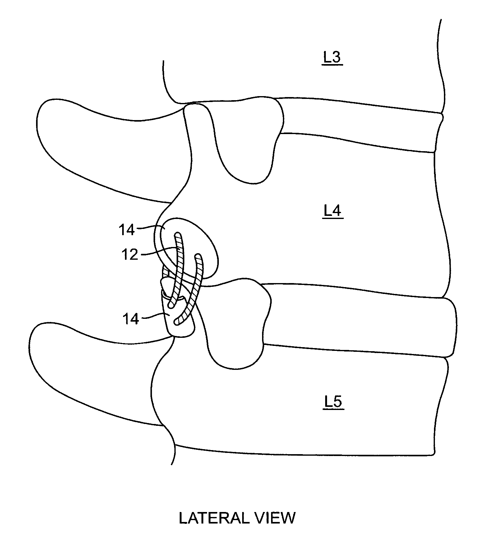
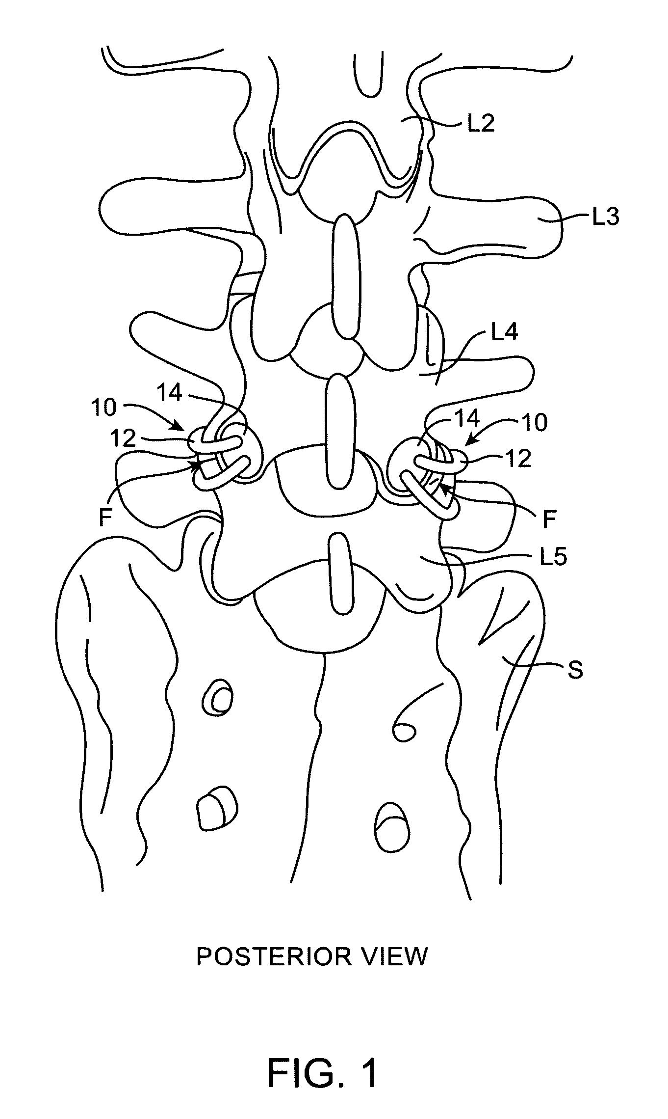
[0045]FIG. 1 is a posterior perspective view of the most inferior four lumbar vertebrae (L2-L5) and a portion of the sacrum S. Attached across the two facet joints F between the L4 and L5 vertebrae is a clamping device 10 according to one embodiment of the present invention. Each clamping device 10 includes a tether 12 and two bone surface contacting members 14 (only one contacting member 14 is visible for each device 10 in FIG. 1.) As is described in further detail below, two holes are drilled through each of the facet joints F of L4 and L5, tethers 12, coupled with bone contacting members 14, are passed through the holes, and tethers 12 are cinched to apply compressive force across the facet joints F, thus promoting fusion of and / or stabilizing the joints F.

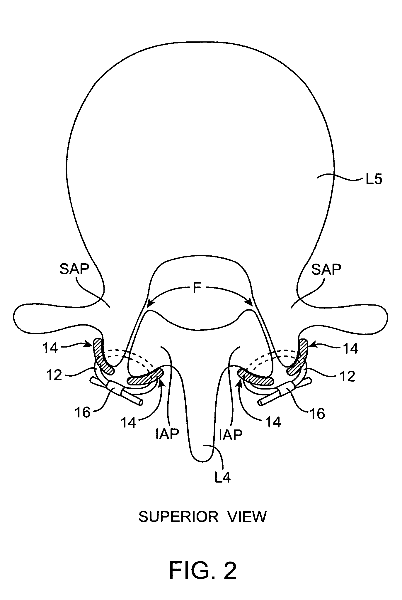
[0046]FIGS. 2 and 3 provide superior and lateral views, respectively, of clamping device 10 from FIG. 1. In FIG. 2, it can be seen that tethers 12 extend through holes (dotted lines) in the vertebrae L4, L5 and across the facet...


PUM


Abstract

A method for promoting fusion of and / or stabilizing a facet joint between two adjacent vertebrae comprises clamping the two adjacent vertebrae across the facet joint to apply a compressive force across the joint. Apparatus for promoting fusion of and / or stabilizing a facet joint comprises at least one cinchable tether and at least one locking member coupled with the tether for locking the cinched tether to maintain compressive force across the facet joint. The tether is adapted to extend through at least one hole through each of two adjacent vertebrae, across the facet joint.

Description

CROSS-REFERENCES TO RELATED APPLICATIONS[0001]This application claims the benefit of provisional application 60 / 581,196, filed on Jun. 17, 2004, the full disclosure of which is incorporated herein by reference.BACKGROUND OF THE INVENTION[0002]The present invention relates to medical devices, methods and systems. More specifically, the invention relates to devices, methods and systems for promoting fusion of and / or stabilizing a facet joint of a spine.[0003]Approximately 80% of Americans experience at least a single episode of significant back pain in their lifetime. For many people, back pain is a chronic, often debilitating disorder. The direct costs of treating back pain, as well as the indirect costs, such as lost wages and decreased productivity, are staggering.[0004]Although back pain may be caused by a number of different factors, many cases of back pain are caused by conditions related to the spinal (or “vertebral”) column. The vertebral column is made up of bones (vertebrae)...

Claims


Application Information

Patent Timeline
Patent Type & Authority Patents(United States)
IPC IPC(8): A61B17/56A61B17/70A61B17/80A61F2/44
CPCA61B17/842A61B17/7064A61B17/7053
Inventor ALAMIN, TODD F.CHEE, URIEL HIRAM
Owner ALAMIN TODD F
Why Eureka
Try Eureka