[0008]Am object of the present invention is to improve an orthopedic device having two components that are mounted so as to be movable (e.g., longitudinally displacable, pivotable, etc.) with respect to one another and any sensors or actuators assigned to them in such a way that a sufficient supply of power is ensured and as lightweight a design as possible is achieved.
[0010]These high amounts of energy are derived from the impulse that occurs in the taking of a step and absorption of the body weight and the leverage ratio at the joint in question. Likewise, in other prosthetic or othotic devices, such as in the upper extremities or in a lumbar orthesis, high bending moments may occur. In order to be able to use these short-term energy infusions, a transmitting mechanism is provided that converts a translatory or rotational movement in such a way that a generator for generating electric power is driven in a preferably rotational manner. This drive is preferably configured in such a way that only one direction of rotation is possible for the generator drive shafts so as to minimize the effort involved in reversing the generator's direction of rotation. Likewise, by using a drive in only one direction of rotation, an energy accumulator, in particular a spring, can be more easily impinged, in particular loaded, and used effectively. The generator is preferably designed as an alternating current generator that is attached to the orthesis or prosthesis and supplies energy to the components that consume energy, such as actuators or sensors. The generator here operates according to the dynamo principle of electromagnetic induction and can alternatively be designed as a direct current generator.
[0011]Another way to make the provision of energy more consistent is to connect an energy accumulator in series with the generator. The energy accumulator is preferably designed as a spring, especially a helical or coil spring, and is used to smooth or collect movement impulses. Such springs are sufficiently well known from clock design and ensure that the generator is powered via the gear unit at a correspondingly high rotational speed as long as the pretensioning of the spring is high enough. Because both the gear unit and the generator are kept in motion by the energy accumulator, no cohesive friction effects or startup losses occur, which further increases the efficiency. To increase the efficiency and to make the drive of the generator more consistent, a gear unit is preferably connected in series with the generator and transmits the relatively short length of movement of two components that are pivotable with respect to one another into a rotational speed adapted to the generator.
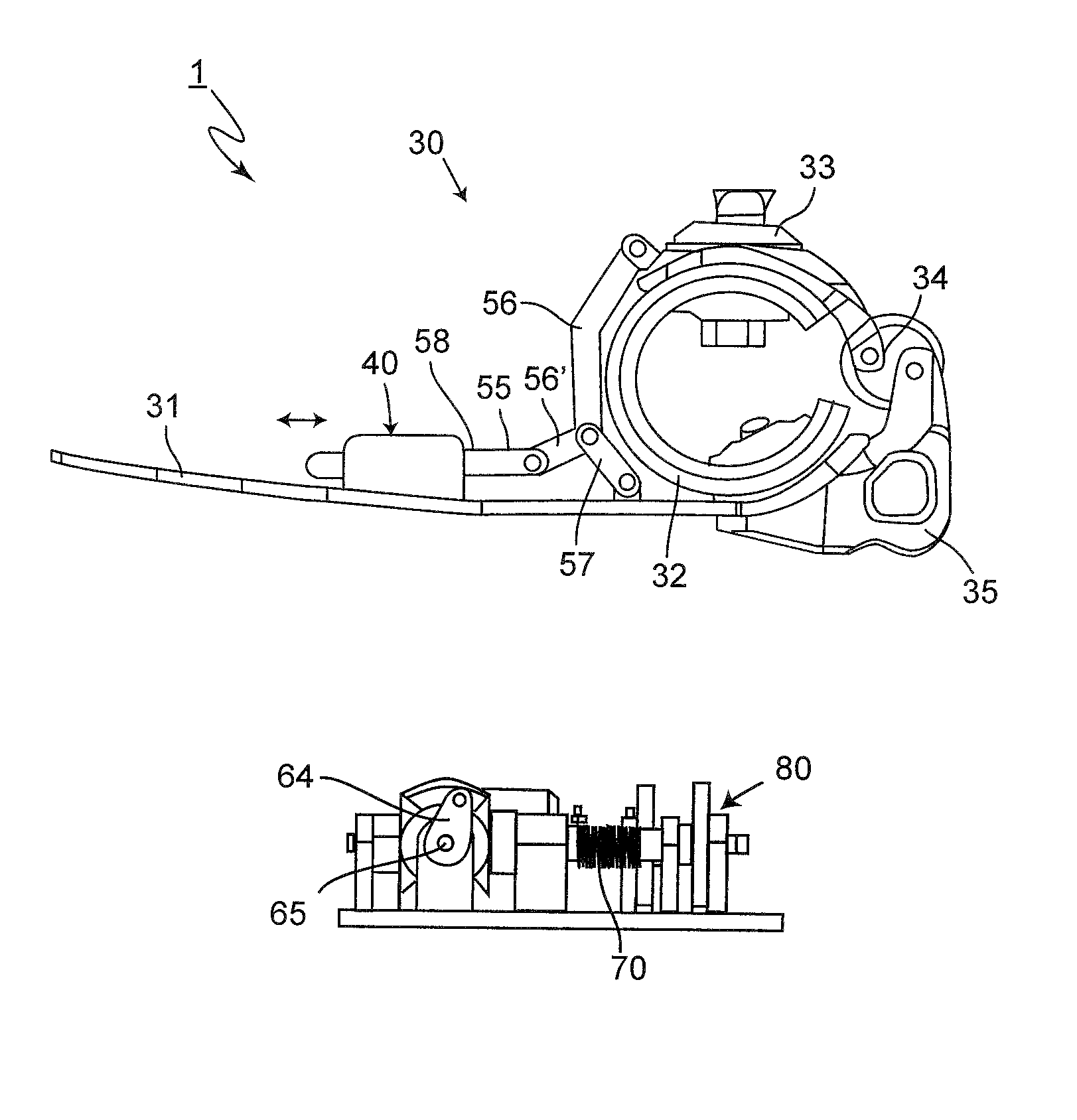
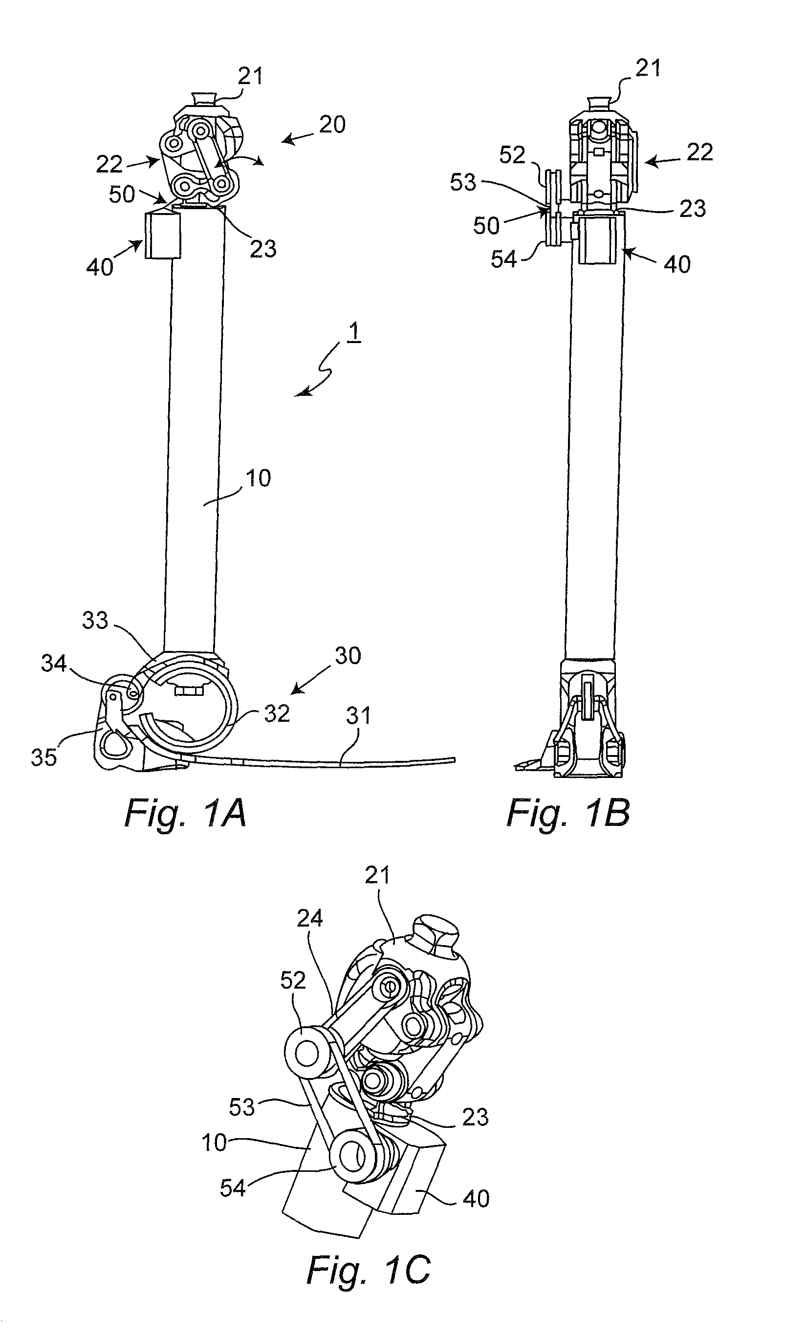
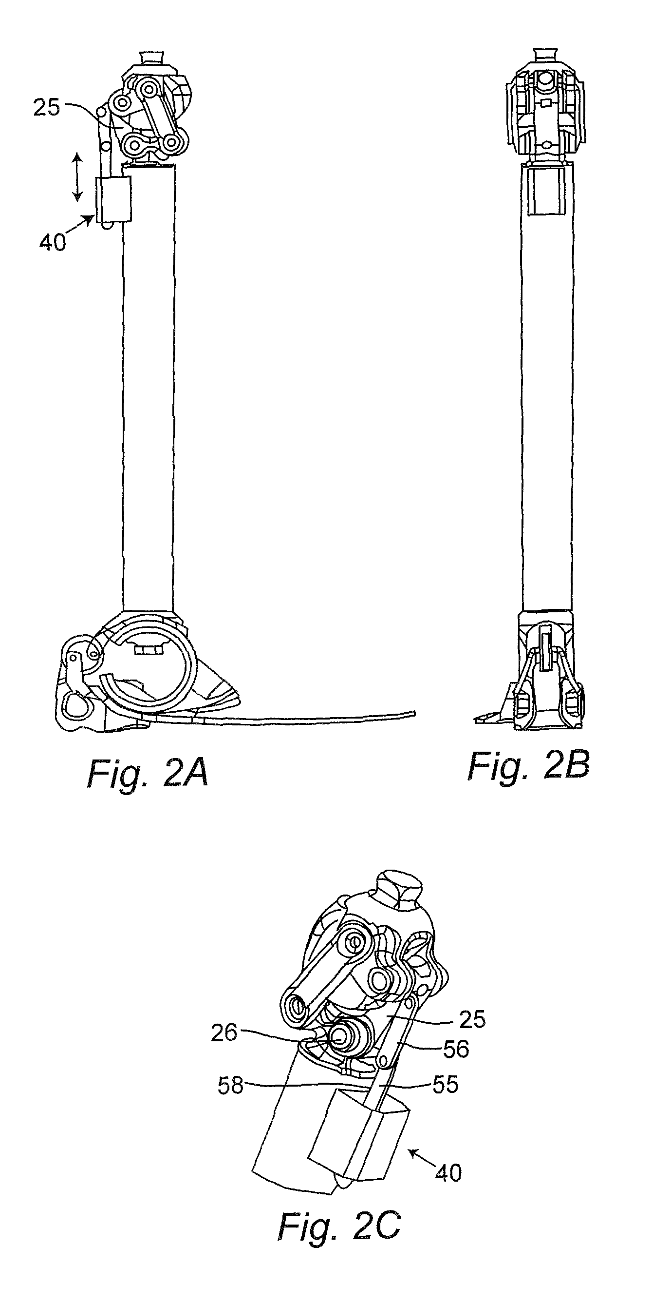
[0014]In one embodiment of the invention, it is provided that the transmitting mechanism has a connecting rod that converts a rotation of two components, such as a foot portion and a lower leg portion or an upper portion and a lower portion of a knee joint device, into a translatory motion. This translatory motion is alternating, where a corresponding control of the connecting rod ensures that a drive of the generator or an impingement of an energy storage device occurs in only one direction. The connecting rod makes it possible to realize a conversion, so that the relatively small rotational angle can be converted into large translatory movements. Likewise, it is possible for the connecting rod to be connected to the generator via a joint mechanism or to the gear unit connected in series with the generator.
[0016]Moreover, it is possible that the transmitting mechanism has a dual gear arrangement with at least one switching device that produces or enables a transmission of force on a driven shaft only in one direction of rotation, so that the gears are active in one direction of force. Here, it is provided that a reversal of direction occurs on a gear, most simply via an interposed gear, to ensure a uniform direction of rotation for the driven shaft and, thus, the generator. A corresponding switching or, for example, a sliding block guide makes it possible for translatory or rotational movements in different directions each to be transmitted to a gear that, via suitable transmission mechanisms, rotates the drive shaft only in one direction of rotation and in the other direction is blocked or not driven at all. Instead of a switching of the gears, they can also be provided with a freewheel and driven simultaneously, where one gear is provided with a device for reversing the direction of rotation so that, when there are alternating movements, drive occurs only in one direction.
[0018]The generator can be coupled with a battery or with a capacitor in order to provide, in addition to a mechanical storage of energy, also an electrical storage of energy. When an alternating current generator is used, a rectifier needs to be provided to charge a battery. Especially when there is an interposed spring, a constant drive can be controlled via an additional mechanical brake. It is also possible to control the output drive via a short-circuit protection circuit in the generator. Via constant drive of the generator, an essentially steady generation of energy is possible, so that a transformer can be omitted, which has positive effects on both the structural size and the weight.

