Image pickup system, including measuring unit

Active Publication Date: 2014-07-08
CANON KK
View PDF6 Cites 1 Cited by
  • Summary
  • Abstract
  • Description
  • Claims
  • Application Information

AI Technical Summary

Benefits of technology

[0012]Therefore, an object of the present invention is to provide an image pickup system that can perform less-blurred focusing on an object in the optical axis direction of the image pickup optical system a

Problems solved by technology

During panning/tilting, the object is sequentially changed from one to another, resulting in instability of a focal position of a focus lens unit.
Also, during panning/tilting operation to the target panning/tilting positions using a shot function, autofo

Method used


Image

  • Image pickup system, including measuring unit
  • Image pickup system, including measuring unit
  • Image pickup system, including measuring unit

Examples


embodiment 1

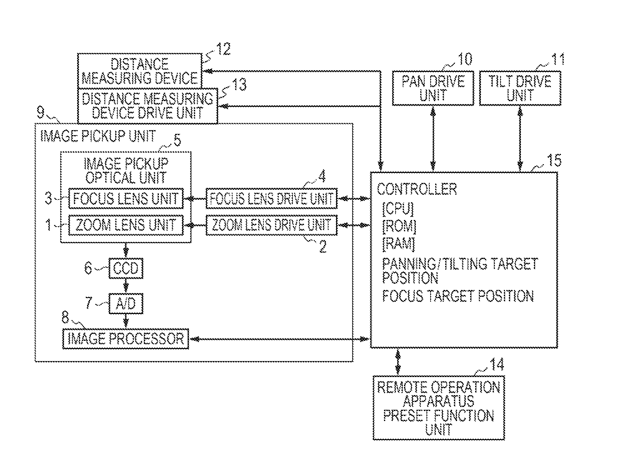
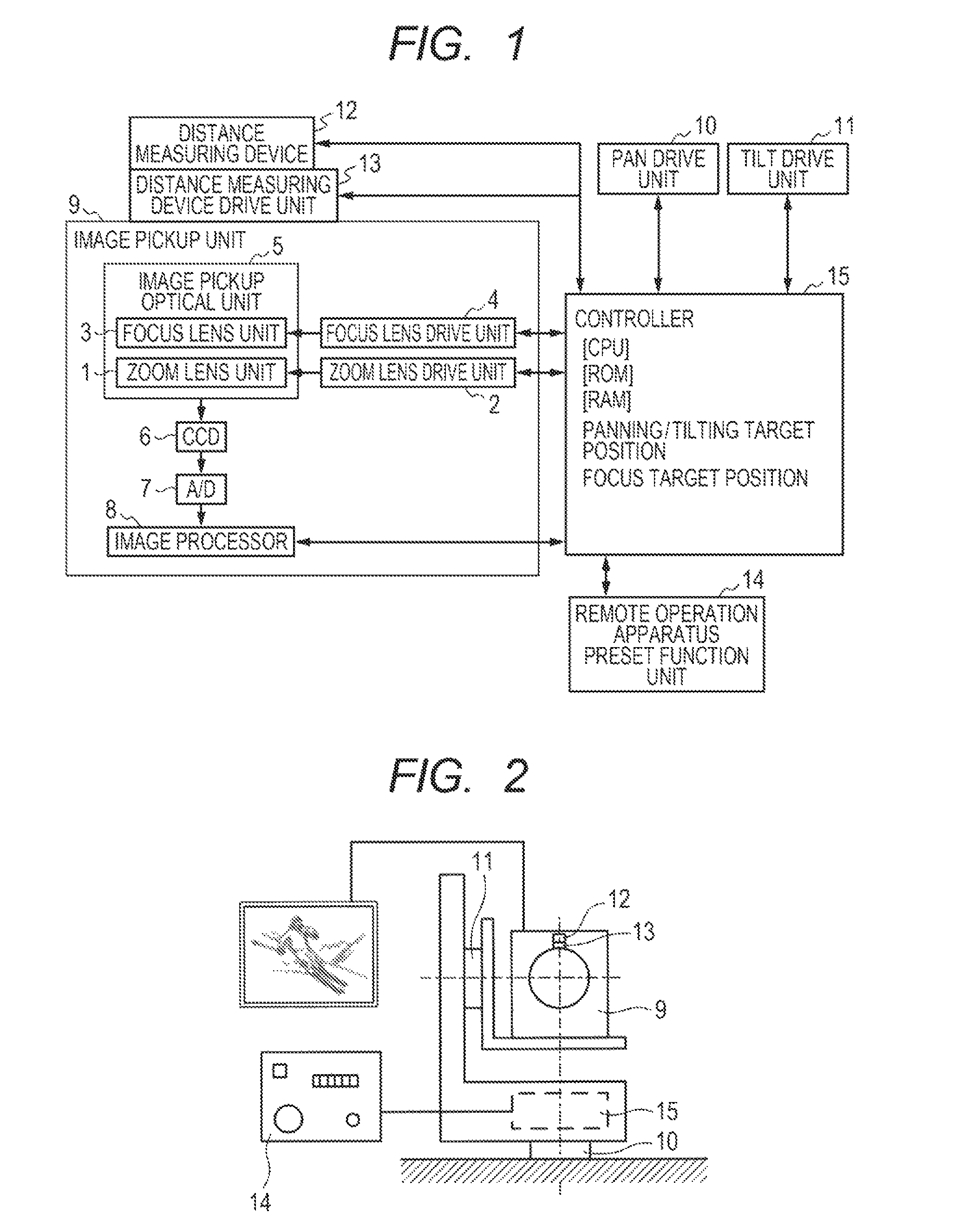
[0023]Hereinafter, a first embodiment of the present invention will be described with reference to FIGS. 1 and 2. First, a configuration of an image pickup system, which is illustrated in FIG. 1, will be described.

[0024]An image pickup system according to the present embodiment includes: an image pickup unit 9 including an image-pickup optical unit (image pickup optical system) 5 including a zoom lens unit 1 for changing a magnification for image pickup and a focus lens unit 3 for focus adjustment and an image sensor 6 such as a CCD (hereinafter referred to as CCD 6) that photoelectrically converts an image of an object picked up by the image-pickup optical unit 5 to an image signal; a pan drive unit 10 that drives the image pickup unit 9 to pan; a tilt drive unit 11 that drives the image pickup unit 9 to tilt; a controller 15 that controls driving of the entire image pickup system; and a remote operation apparatus 14 that is connected to the controller 15 and remotely operates the ...

embodiment 2

[0052]Hereinafter, a second embodiment of the present invention will be described with reference to FIGS. 1, 5 and 6.

[0053]For a configuration of the image pickup system according to embodiment 2, FIG. 1 should be referred to because the configuration is similar to the configuration of embodiment 1.

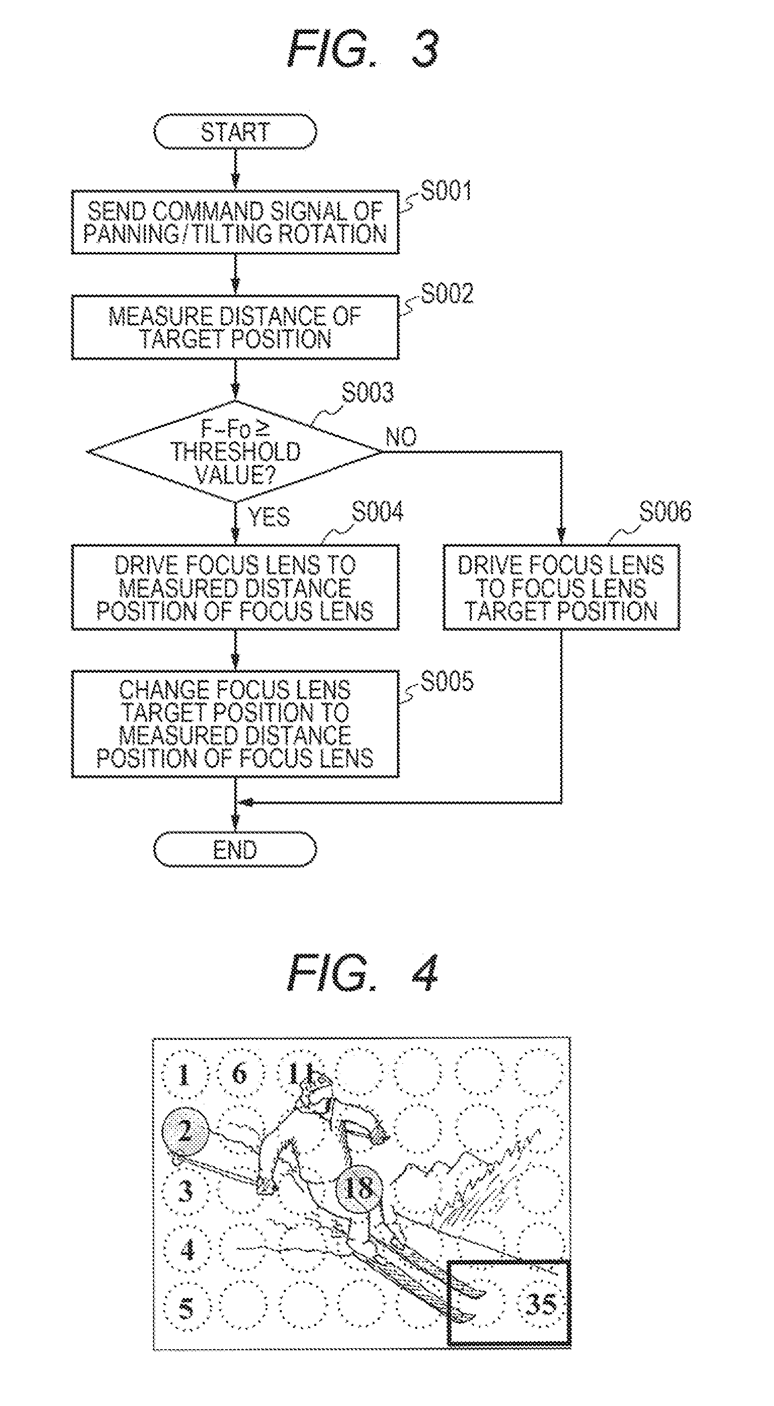
[0054]A case where no position command signal is input from a remote operation apparatus 14 to a controller 15 will be described. In this case, a distance measuring device drive unit 13 does not rotate for panning / tilting. When no position command signal is input, a command signal is transmitted from the controller 15 to the distance measuring device drive unit 13 to control the driving of the distance measuring device 12 so that a panning position of the distance measuring device 12 corresponds to a panning position of the image pickup unit 9. The distance measuring device 12, which includes one pair of line sensors, measures a distance to an object at fixed time intervals and outputs a ...


PUM


Abstract

An image pickup system includes: an optical system including a focus lens unit; a camera platform apparatus driving the optical system to pan and tilt; a measuring unit measuring a distance to an object, the measuring unit operable to be driven independently from the pan/tilt-driving of the optical system; and a controller storing panning/tilting positions of the optical system as pre-set positions, and controls driving of the optical system to the pre-set positions, wherein upon input of a drive command for driving the optical system to the stored pre-set positions, the controller drives the measuring unit so that a panning position of the measuring unit and the stored panning position correspond to each other and starts measurement by the measuring unit before completion of the driving of the optical system to the stored panning/tilting positions.

Description

BACKGROUND OF THE INVENTION[0001]1. Field of the Invention[0002]The present invention relates to an image pickup system including a camera platform apparatus, and specifically relates to an image pickup system having a function that stores panning / tilting positions of a camera platform apparatus and drives the camera platform apparatus to the stored panning / tilting positions.[0003]2. Description of the Related Art[0004]Conventionally, camera platform apparatuses that pan / tilt using remote control from a remote operation apparatus in image pickup systems including an autofocusing unit have been known.[0005]For autofocusing when a camera platform apparatus is used, an arbitrary area of an image pickup screen is made to a region subject to autofocusing, and an image pickup lens for focusing is driven according to a distance to an object in the region. Then, upon the camera platform apparatus being panned / tilted, the object on camera is changed from one to another and the focus state ch...

Claims


Application Information

Patent Timeline
IPC IPC(8): G03B13/00H04N5/232
CPCH04N5/23212H04N5/23296H04N23/67H04N23/69H04N23/695
Inventor HIRAI, YUUSUKE
Owner CANON KK
Why Eureka
Try Eureka