Motorized wheelchair interlock

a motorized wheelchair and interlocking technology, applied in the field of motorized wheelchair interlocking devices, can solve problems such as the operator losing the delectable devi

Inactive Publication Date: 2014-07-08
PHILLIPS ALAN C +2
View PDF36 Cites 15 Cited by
  • Summary
  • Abstract
  • Description
  • Claims
  • Application Information

AI Technical Summary

Problems solved by technology

When the detectable component is moved away from the sensor the interlock switch does not allow the inputs of the joystick to be transmitted to the wheel chair control system.
In a worst case scenario the operator lost the delectable device.

Method used


Image

  • Motorized wheelchair interlock
  • Motorized wheelchair interlock
  • Motorized wheelchair interlock

Examples


Embodiment Construction

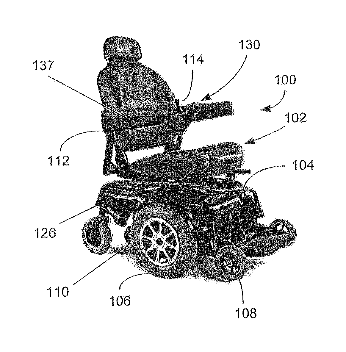
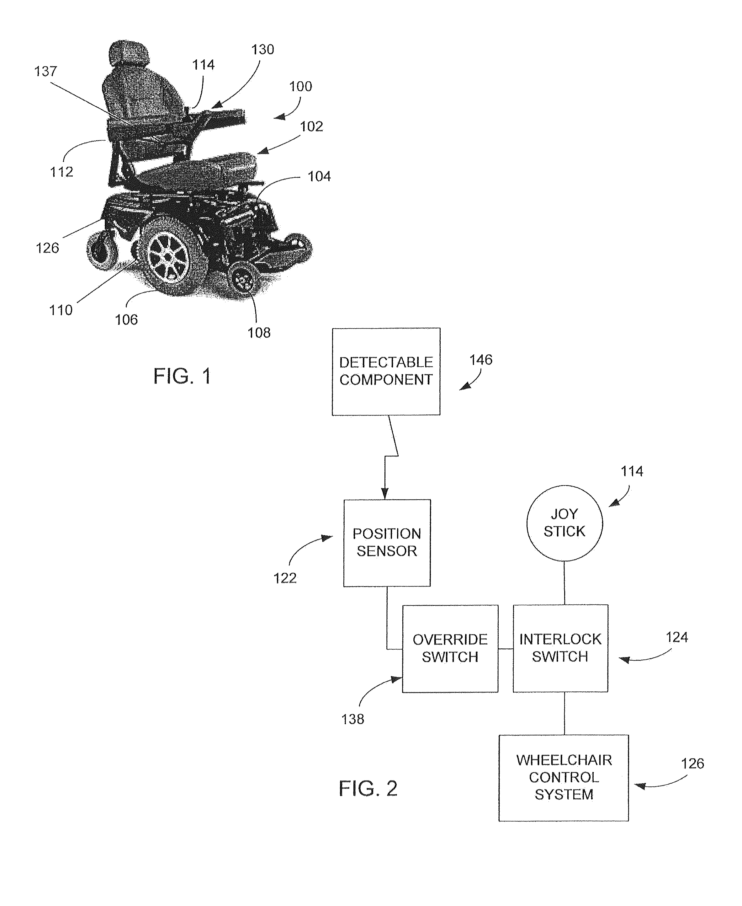
[0024]Reference will now be made to the drawings wherein like numerals refer to like parts throughout. Referring to FIG. 1, an exemplary motorized wheelchair 100 is illustrated. As indicated, the wheelchair 100 includes a seat 102 that accommodates the user. The seat is mounted on a chassis 104 that is attached to primary driving wheels 106 and secondary wheels 108. The chassis also accommodates a battery powered motor 110 that provides power to the driving wheels 106 for motion or turning.

[0025]In this implementation, the wheelchair 100 also includes armrests 112 and one of the armrests incorporates, in this embodiment, a wheelchair control unit 130 which contains a joystick 114.

[0026]The wheel chair control unit 130 is preferably positioned in a location that is easily accessible to the user such as in front of one of the armrests 112. The control system 126 which provides inputs to the motor 110 is housed discreetly in the rear or under the seat and is attached to the control uni...


PUM

PropertyMeasurementUnit
movement controlaaaaaaaaaa
movementaaaaaaaaaa
stabilityaaaaaaaaaa

Abstract

A control system for a powered wheelchair that detects when a user is in a first orientation to cause movement of the powered wheelchair. The control system inhibits movement of the wheelchair when the user is not in the first orientation.

Description

[0001]This application claims the benefit of U.S. Provisional Patent Application Ser. No. 61 / 600,526, filed Feb. 17, 2012.FIELD OF THE INVENTION[0002]The present invention relates to wheelchairs and, in particular, concerns an interlock device that inhibits unintentional movement of the wheelchair,BACKGROUND OF THE INVENTION[0003]Motorized wheelchairs are becoming, increasingly popular for people with ambulatory difficulties. Typically, these chairs include a chair that receives a user and typically two or more sets of wheels. Generally, the set of drive wheels are individually powered by motors and the secondary set of wheels are casters for stability. The motors can provide variable amounts of power to each of the wheels so that providing the same amounts of power to both wheels propels the wheelchair forward or backward. The wheelchair can be made to turn by applying more power to one wheel than the other. The exact manner in which a wheelchair is steered and powered can, of cour...

Claims


Application Information

Patent Timeline
Patent Type & Authority Patents(United States)
IPC IPC(8): G05D1/00G06F7/00G05D3/00B60L11/00G06F17/00B60L9/00
CPCA61G2203/14A61G5/043Y02T10/70B60L2200/24B60L15/30Y02T10/7005B60L11/1805A61G2203/40A61G2203/36A61G2203/20Y02T90/121Y10T29/49117Y02T10/7275B60L50/52Y02T10/64Y02T10/72
Inventor PHILLIPS, ALAN C.PHILLIPS, CRAIG A.FISHER, KEVIN C.
Owner PHILLIPS ALAN C
Why Eureka
Try Eureka